
Non-structural matrix grid and crack connectivity detection method and device, and medium

A detection method, non-structural technology, applied in the direction of structured data retrieval, image data processing, special data processing applications, etc., can solve the geometric complexity of unstructured grids to increase computational overhead, take tens of minutes to several hours, Reduce problems such as engineering analysis and simulation efficiency, achieve the effects of reducing intersection detection operations, reducing computational complexity, and accelerating efficiency

Pending Publication Date: 2022-01-07
CHINA UNIV OF PETROLEUM (EAST CHINA)
View PDF0 Cites 4 Cited by
  • Summary
  • Abstract
  • Description
  • Claims
  • Application Information

AI Technical Summary

Problems solved by technology

[0003] At present, traditional fast connectivity detection technologies are developed on the basis of structured grids. In unstructured grids, since the 3D data of vertices of each grid are independent and unrelated, traditional methods cannot be used to accelerate Detection process
Unstructured grids have been widely used in geological and geotechnical engineering modeling in recent years. The geometric complexity of unstructured grids has greatly increased the computational overhead for connectivity detection with internal fractures. For each fracture, it is often necessary to traverse the entire grid system. In an unstructured grid system with a number of more than one million, it usually takes tens of minutes to several hours to detect the connectivity between the unstructured matrix grid and the fracture grid. , which seriously reduces the efficiency of engineering analysis and simulation

Method used


Image

  • Non-structural matrix grid and crack connectivity detection method and device, and medium
  • Non-structural matrix grid and crack connectivity detection method and device, and medium
  • Non-structural matrix grid and crack connectivity detection method and device, and medium

Examples


Embodiment Construction

[0046] The following will clearly and completely describe the technical solutions in the embodiments of the present invention with reference to the accompanying drawings in the embodiments of the present invention. Obviously, the described embodiments are only some, not all, embodiments of the present invention. Based on the embodiments of the present invention, all other embodiments obtained by persons of ordinary skill in the art without making creative efforts belong to the protection scope of the present invention.

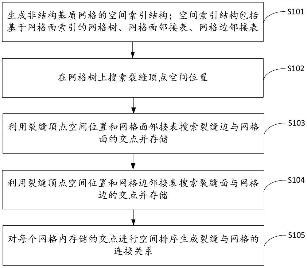
[0047] The invention provides a method for detecting the connectivity between grids and fractures of non-structural matrix, such as figure 1 shown, including the following steps:

[0048] S101. Generate a spatial index structure of an unstructured matrix grid; the spatial index structure includes a grid tree based on a grid face index, a grid face adjacency list, and a grid edge adjacency list;

[0049]It should be noted that before the connectivity detection...


PUM


Abstract

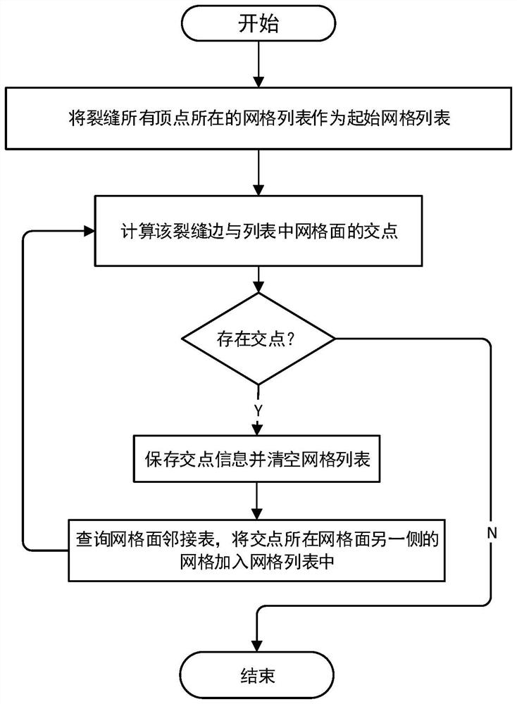
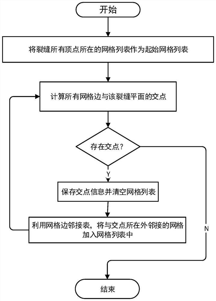
The invention discloses a non-structural matrix grid and crack connectivity detection method and device, and a medium. The method comprises the steps of: generating a spatial index structure of a non-structural matrix grid, wherein the spatial index structure comprises a grid tree based on a grid surface index, a grid surface adjacency list and a grid edge adjacency list; searching a spatial position of a crack vertex on the grid tree, searching and storing intersection points of crack edges and a grid surface by using the grid surface adjacency list, and searching and storing intersection points of a crack surface and grid edges by using the grid edge adjacency list; and performing spatial sorting on the intersection points stored in each grid to generate a connection relationship between a crack and the grid. In this way, the calculation complexity can be effectively reduced, the calculation process can be accelerated, the grids which may intersect around the crack can be rapidly selected by using the generated connection relation, the intersection detection operation is reduced, grid traversal is avoided, and then the efficiency of matrix grid and crack connectivity detection is effectively improved.

Description

technical field [0001] The invention relates to the technical field of rock detection, in particular to a method, device and medium for detecting the connectivity between a non-structural matrix grid and a fracture. Background technique [0002] Fractured rocks widely exist in petroleum, geological and geotechnical engineering, and the detection of connection properties between fractures and bedrock grids is a necessary step for analyzing various engineering problems and performing rock flow simulation. [0003] At present, traditional fast connectivity detection technologies are developed on the basis of structured grids. In unstructured grids, since the 3D data of vertices of each grid are independent and unrelated, traditional methods cannot be used to accelerate detection process. Unstructured grids have been widely used in geological and geotechnical engineering modeling in recent years. The geometric complexity of unstructured grids has greatly increased the computati...

Claims


Application Information

Patent Timeline
Patent Type & Authority Applications(China)
IPC IPC(8): G06T17/20G06F16/22
CPCG06T17/20G06F16/2246G06F16/2282
Inventor 王通姚军
Owner CHINA UNIV OF PETROLEUM (EAST CHINA)
Learn More