Surgical head clamp

a head clamp and surgical technology, applied in the field of surgical head clamps, can solve the problem of inability to freely move the threaded spindle, and achieve the effect of simple adjustment and fixing of the adjustable mandrel holder, convenient handling and simple construction

Inactive Publication Date: 2007-10-25
GOTTFRIED STORZ MEDIZINTECHN
View PDF6 Cites 47 Cited by
  • Summary
  • Abstract
  • Description
  • Claims
  • Application Information

AI Technical Summary

Benefits of technology

[0011]The basic object of the present invention is to create a surgical head clamp of the type mentioned in the introduction, which, with a simpler construction, makes possible an easier handling, in particular a simpler adjustment and fixing of the adjustable mandrel holder and with gentle action, a better fixing of a patient's head, whereby the threaded spindle shall be freely displaceable in the holder arm with abolishing of the threaded contact.

Problems solved by technology

In the prior-art head clamps, in which the hollow threaded spindle detachably meshes with an internal thread of the bearing bore of the clamp arm, a free displacement of the threaded spindle is not possible.

Method used


Image

  • Surgical head clamp
  • Surgical head clamp
  • Surgical head clamp

Examples


Embodiment Construction

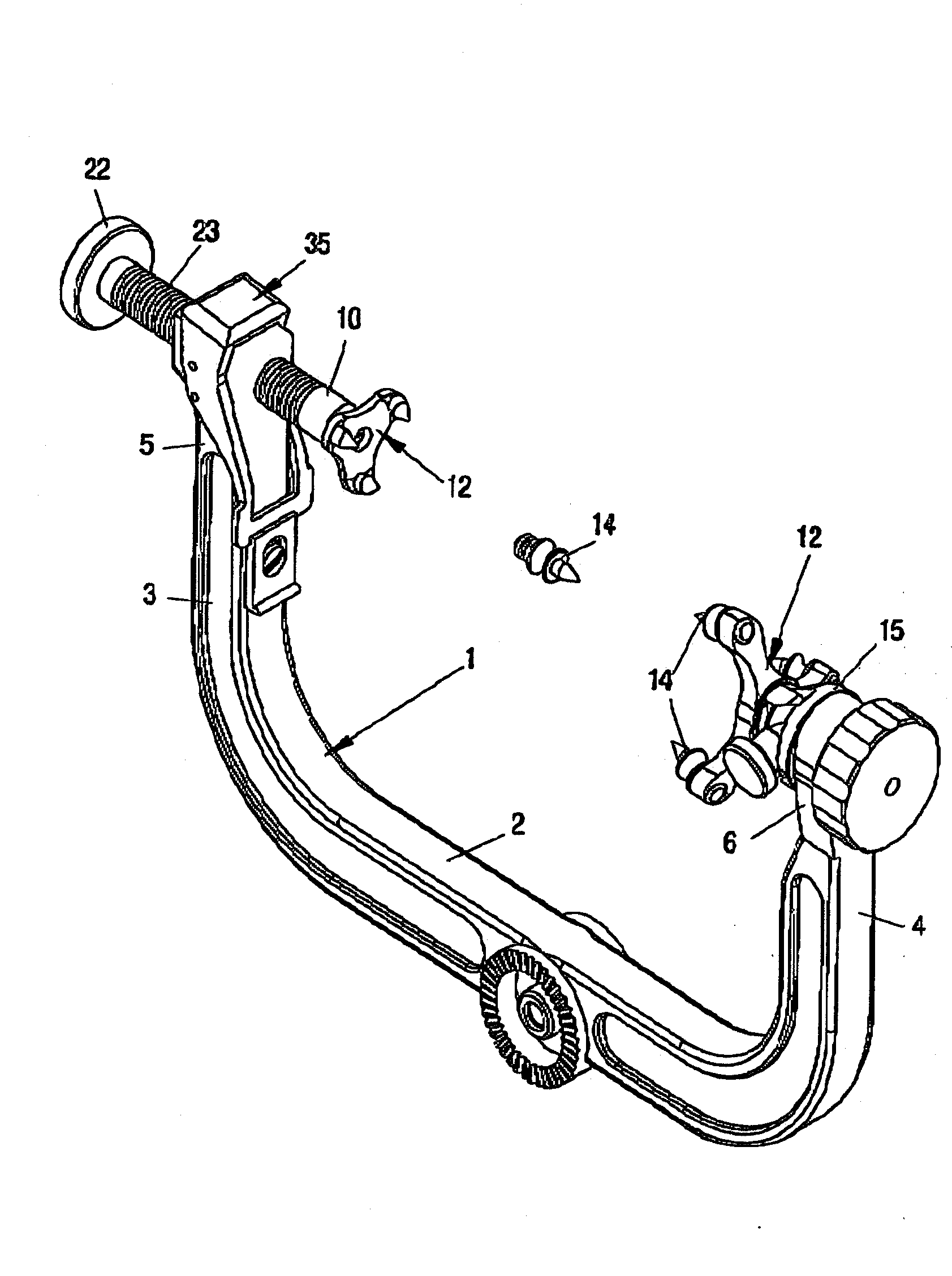
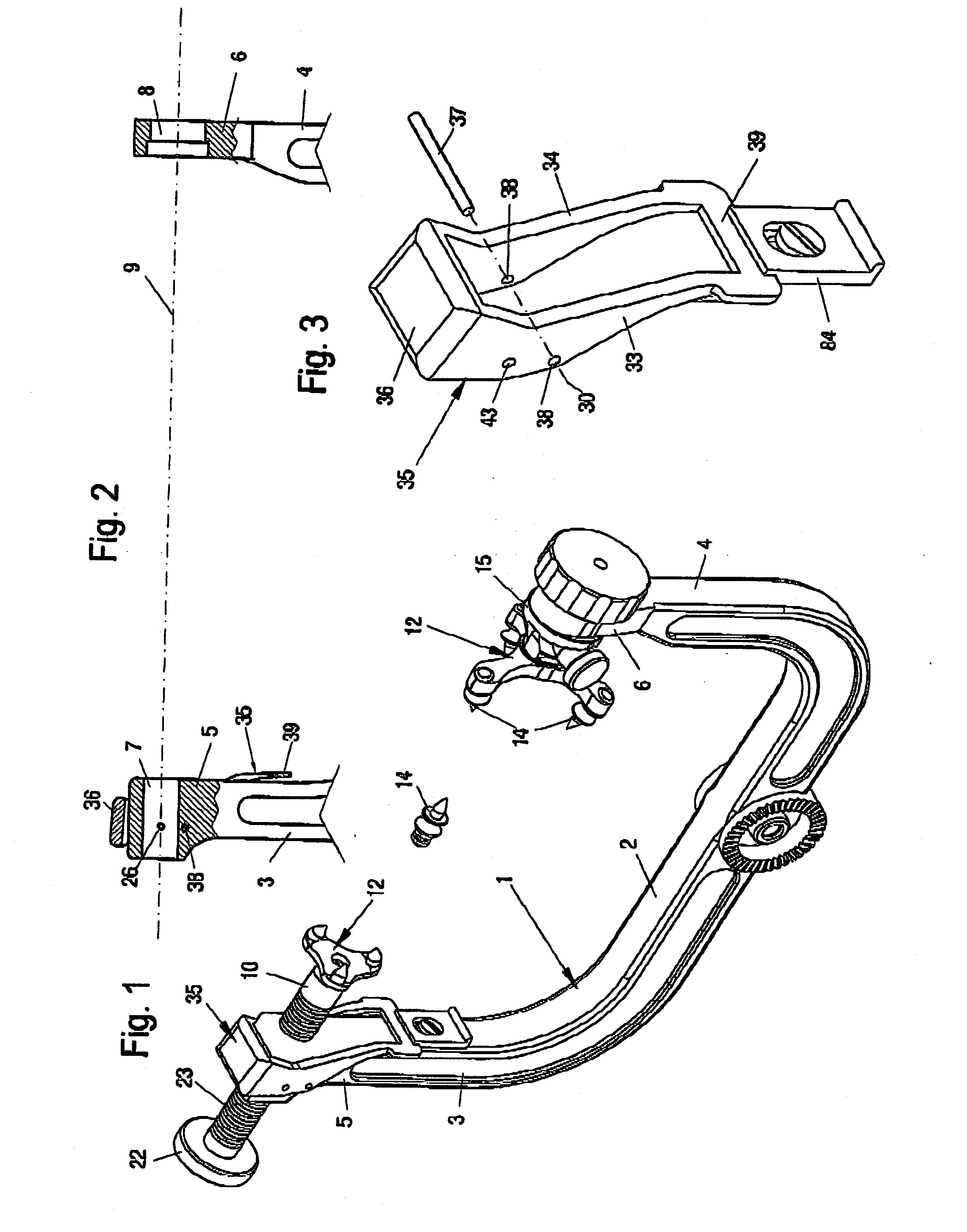
[0035]Referring to the drawings in particular, the head clamp shown in the drawing figures comprises a U-shaped retaining clip 1, which has holder arms 3 and 4 running towards the same side at the ends of a single-part connecting bar 2 in the plane thereof.

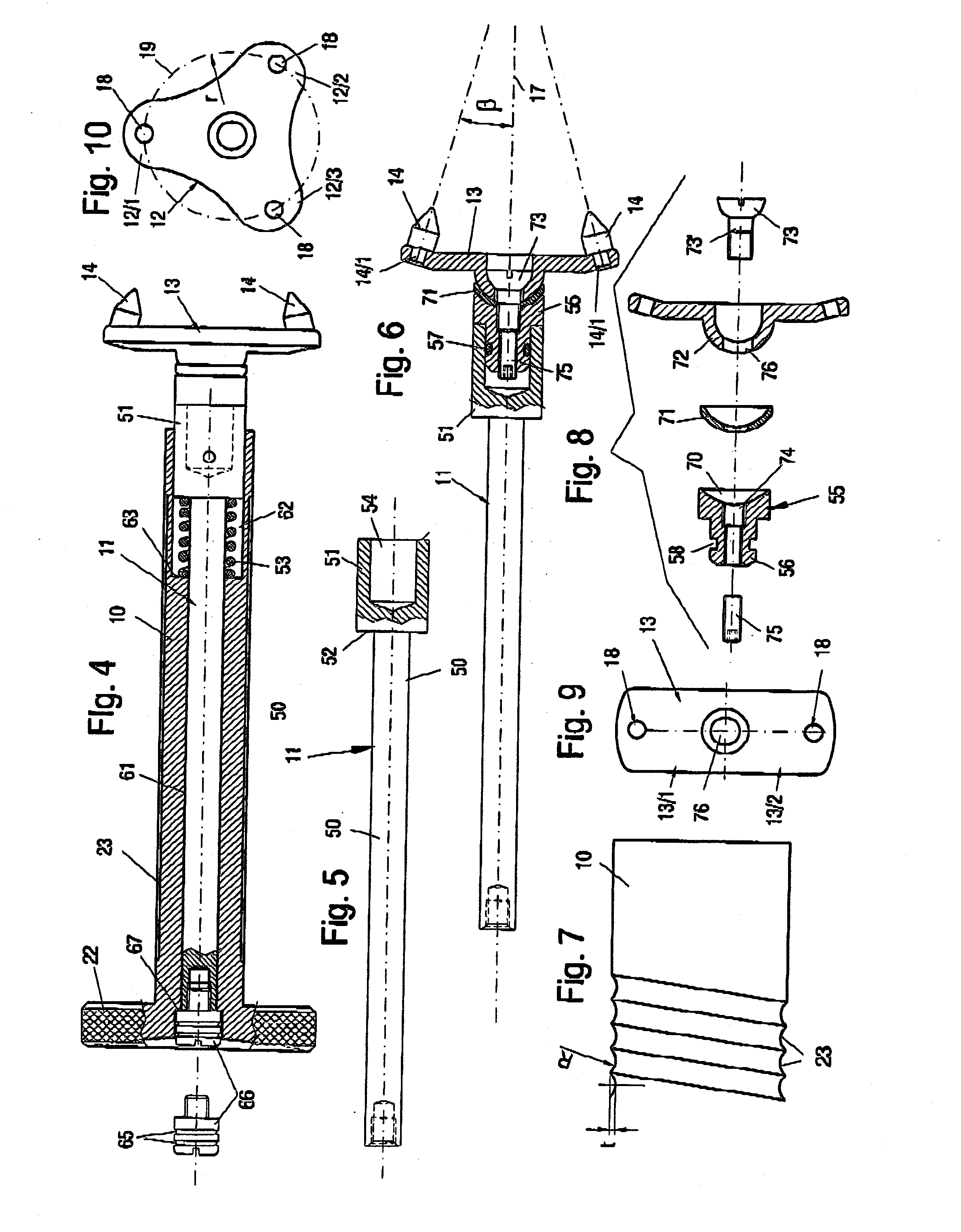
[0036]The upper ends 5 and 6 of the holder arms 3 and 4 are each provided with bearing bores 7 and 8, respectively, that are coaxial to one another, which have a common bearing shaft 9 (see FIG. 2). The bearing bore 7 is used for mounting and guiding a threaded spindle 10, in which is mounted a mandrel holder 11 (FIGS. 4 through 6). This mandrel holder 11 is provided with a three-arm mandrel carrier 12 in the embodiment shown in FIG. 1. However, as described in further detail below, it may be provided either with a two-arm mandrel carrier 13 or with a single holding mandrel 14 that is coaxial to the bearing shaft 9.

[0037]The opposite bearing bore 8 of the other holder arm 4 is used for mounting a bearing part 15, at which either a...


PUM


Abstract

A surgical head clamp is provided including an essentially U-shaped retaining clip (1) with two holder arms (3, 4), running towards the same side in the plane thereof at the ends of a connecting bar (2). The arm ends (5, 6) of the holder arms have mandrel holders (11) mounted adjustably in bearings that are coaxial to one another. The mandrel holders may be provided with one or more said holding mandrels (12), whereby a first mandrel holder is pivotably fastened at a bearing part (15) of the one arm end (6), which bearing part is adjustable around a common bearing shaft (9), and a second mandrel holder (11) can be adjusted by means of a threaded spindle (10) in a bearing bore (7) of the other said arm end (5). The second mandrel holder (11) includes a guide shank (50) that is provided with a socket bore (54) on the front side, which is mounted coaxially to the bearing shaft (9) in a spring-mounted manner in a axial bore (61) of the threaded spindle (10). The threaded spindle (10) is provided with an external thread and is adjustably mounted in a smooth cylindrical bearing bore (7) of the other arm end (3). The external thread is embodied as a ball thread (23), which has an arcuate-segment profile, with which two balls (24, 25) mesh as contact elements. The balls are arranged in a diametrically opposed, axially fixed manner in the wall (28) of the bearing bore (7) and are held in contact with the ball thread (23) by an adjustable locking lever (35) in the locked position thereof, and which can be brought out of contact with the threaded spindle (10) in another position in order to make the threaded spindle (10) freely displaceable in its said bearing bore (7).

Description

CROSS REFERENCE TO RELATED APPLICATIONS[0001]This application claims the benefit of priority under 35 U.S.C. §119 of German Patent Application DE 20 2006 006 734.5 filed Apr. 24, 2006, the entire contents of which are incorporated herein by reference.FIELD OF THE INVENTION[0002]The present invention pertains to a surgical head clamp consisting of an essentially U-shaped retaining clip with two holder arms running towards the same side in the plane thereof at the ends of a connecting bar, the arm ends of which holder arms have mandrel holders mounted adjustably in bearings that are coaxial to one another, which mandrel holders may be provided with one or more holding mandrels, whereby a first mandrel holder is pivotably fastened at a bearing part of the one arm end, which bearing part is adjustable around a common bearing shaft, and a second mandrel holder can be adjusted by means of a threaded spindle in the bearing bore of the other arm end.BACKGROUND OF THE INVENTION[0003]A head o...

Claims


Application Information

Patent Timeline
Patent Type & Authority Applications(United States)
IPC IPC(8): A61B19/00
CPCA61B19/203A61B90/14
Inventor SOERENSEN, NIELSZIAJA, HERMANNKREIDLER, WINFRIED
Owner GOTTFRIED STORZ MEDIZINTECHN
Why Eureka
Try Eureka