Method for synchronization of a controller

a controller and controller technology, applied in the field of controller fault recovery, can solve the problems of system operating without sufficient fault tolerance, ineffective solution for cost-constrained systems, and misrepresentation of state, and achieve the effect of reducing additional fault scenarios

Inactive Publication Date: 2007-10-25
GM GLOBAL TECH OPERATIONS LLC
View PDF9 Cites 36 Cited by
  • Summary
  • Abstract
  • Description
  • Claims
  • Application Information

AI Technical Summary

Benefits of technology

[0006] The present invention comprises a method for controller reintegration by synchronizing the output of the primary controller with outputs of the secondary controllers, comprising a self-correcting controller that updates and adapts controller states, thus enabling bringing the controller operation back on-stream in a seamless and simple manner. The invention comprises a passive reintegration mechanism without active intervention of other correctly functioning redundant controllers, thus reducing additional fault scenarios. As such, a system incorporating the invention does not require bursts of profligate communication or memory transfer from other controllers.

Problems solved by technology

Errors may be due to controllers that have temporary faults, or have been reset (e.g., due to a temporary power supply fault), or have drifted out of alignment because of a chaotic system, or wherein different sensor information has been caused by glitches at an input, or wherein there are temporary internal errors due to electromagnetic radiation in memory causing a state to be misrepresented.
This may leave the system operating without sufficient fault-tolerance, even when the faults have subsided.
This may not be an effective solution for cost-constrained systems, including automotive applications.
This problem is especially important since studies have shown that transient faults are likely to occur 5 to 100 times more frequently than permanent faults.
However, such systems require additional hardware, focus on transient memory faults, and are not efficient in managing transient faults that temporarily cause an entire controller to reset.
Additional communication overheads are required to transmit the controller state information that may introduce bus or communication errors.
The controllers need to be transitioned to a different mode to transmit this information which may trigger faults in the remaining working controllers at a time when correct operation is critical.

Method used


Image

  • Method for synchronization of a controller
  • Method for synchronization of a controller
  • Method for synchronization of a controller

Examples


Embodiment Construction

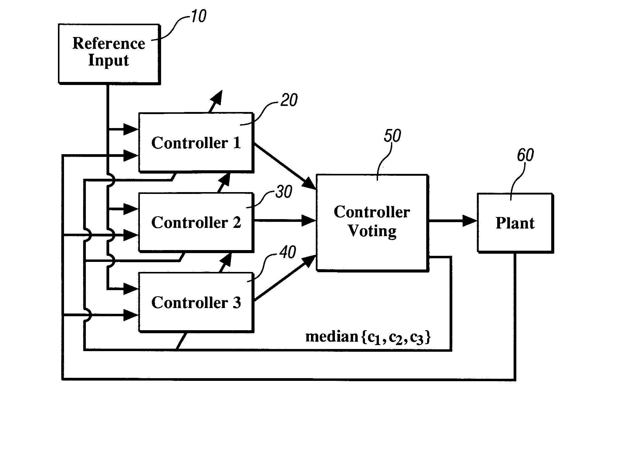
[0028] Referring now to the drawings, wherein the showings are for the purpose of illustrating the invention only and not for the purpose of limiting the same, FIG. 1 shows a triple redundant controller architecture which has been constructed in accordance with an embodiment of the present invention. The triple redundant controller architecture comprises a fault-tolerant control system which is part of an exemplary integrated vehicle control system comprising a distributed control system wherein each controller is signally interconnected via a local area network (‘LAN’) throughout the vehicle to accomplish various tasks.

[0029] Referring again to FIG. 1, the fault-tolerant control system for the exemplary integrated vehicle control system preferably comprises a primary controller 20, and secondary controllers 30, 40, each having an output signal deliverable to a voting mechanism 50, the output of which is an input signal to device 60, to effect control thereof. The output from each ...


PUM


Abstract

A system and method for reintegration of a redundant controller after occurrence of a fault is provided, comprising synchronizing outputs of a primary controller with outputs of secondary controllers. The controller is placed in a different mode of operation in which its output is not used in system control. A meta-controller is activated to drive the primary controller to the same states at which the secondary or redundant controllers operate. A voting mechanism is used to determine a fault in an output to a controlled device. Control of the device using the secondary outputs is effected. The primary controller recalculates the primary output, based upon the primary output; a feedback signal; and, the secondary outputs. Control using the primary output is permitted when the primary output is within an allowable range of the secondary outputs.

Description

TECHNICAL FIELD [0001] This invention pertains generally to control systems, and more specifically to a method for controller fault recovery. BACKGROUND OF THE INVENTION [0002] Safety-critical control systems are increasingly being required, especially with the introduction of full by-wire braking and steering systems in vehicles. These systems need to be robust to controller faults wherein an error may result in loss of a critical vehicle function. Errors may be due to controllers that have temporary faults, or have been reset (e.g., due to a temporary power supply fault), or have drifted out of alignment because of a chaotic system, or wherein different sensor information has been caused by glitches at an input, or wherein there are temporary internal errors due to electromagnetic radiation in memory causing a state to be misrepresented. [0003] One main requirement of these systems is to ensure no single point of failure exists, and as such multiple controllers and actuators are t...

Claims


Application Information

Patent Timeline
Patent Type & Authority Applications(United States)
IPC IPC(8): G05B11/01
CPCG05B9/03
Inventor HOWELL, MARK N.MISHRA, PRADYUMNA K.
Owner GM GLOBAL TECH OPERATIONS LLC
Why Eureka
Try Eureka