Evaporator

a technology of evaporator and evaporator body, which is applied in the direction of indirect heat exchangers, refrigeration components, lighting and heating apparatus, etc., can solve the problems of insufficient draining performance, troublesome assembly of refrigerant flow members and separate fin members, and impairment of heat-exchange performance, so as to improve air flow resistance, improve cooling performance, and enhance the effect of condensed water draining

Inactive Publication Date: 2007-11-01
SHOWA DENKO KK
View PDF2 Cites 30 Cited by
  • Summary
  • Abstract
  • Description
  • Claims
  • Application Information

AI Technical Summary

Benefits of technology

[0038] With the evaporator of par. 11), condensed water which is collected, by the effect of surface tension, on the joint portions between the refrigerant flow members and the wave crest portions and the wave trough portions of the corrugate fins passes through the cutouts of the front projecting portions of the corrugate fins and flows while being attracted, by the effect of surface tension, toward internal corner portions each defined by the front end surface of the front-end flat, hollow member and the front projecting portion of the corrugate fin. Subsequently, the condensed water flows downward along the internal corner portions and is then drained away. Accordingly, drainage of condensed water is enhanced, thereby preventing splashing of condensed water from front end portions of the refrigerant flow members at the time of an abrupt change in air flow rate; a drop in cooling performance caused by an increase in air flow resistance which, in turn, is caused by surface tension causing condensed water to block openings between the louvers; and freezing of condensed water.
[0039] With the evaporator of par. 12), condensed water which is collected, by the effect of surface tension, on the joint portions between the refrigerant flow members and the wave crest portions and the wave trough portions of the corrugate fins passes through the cutouts; flows downward along the portions of the refrigerant flow members located between adjacent front and rear flat tubes of the refrigerant members; and is drained away. Accordingly, drainage of condensed water is enhanced, thereby preventing splashing of condensed water from front end portions of the refrigerant flow members at the time of an abrupt change in air flow rate; a drop in cooling performance caused by an increase in air flow resistance which, in turn, is caused by surface tension causing condensed water to block openings between the louvers; and freezing of condensed water.
[0040] With the evaporator of par. 13), condensed w

Problems solved by technology

However, in the case where the quantity of condensed water is large, drainage performance may become insufficient.
This, in manufacture of the evaporator, raises a problem that assembling together the refrigerant flow members and the separate fin members is troublesome.
Also, a

Method used


Image

  • Evaporator
  • Evaporator
  • Evaporator

Examples


embodiment 1

[0047] The present embodiment is illustrated in FIGS. 1 to 10.

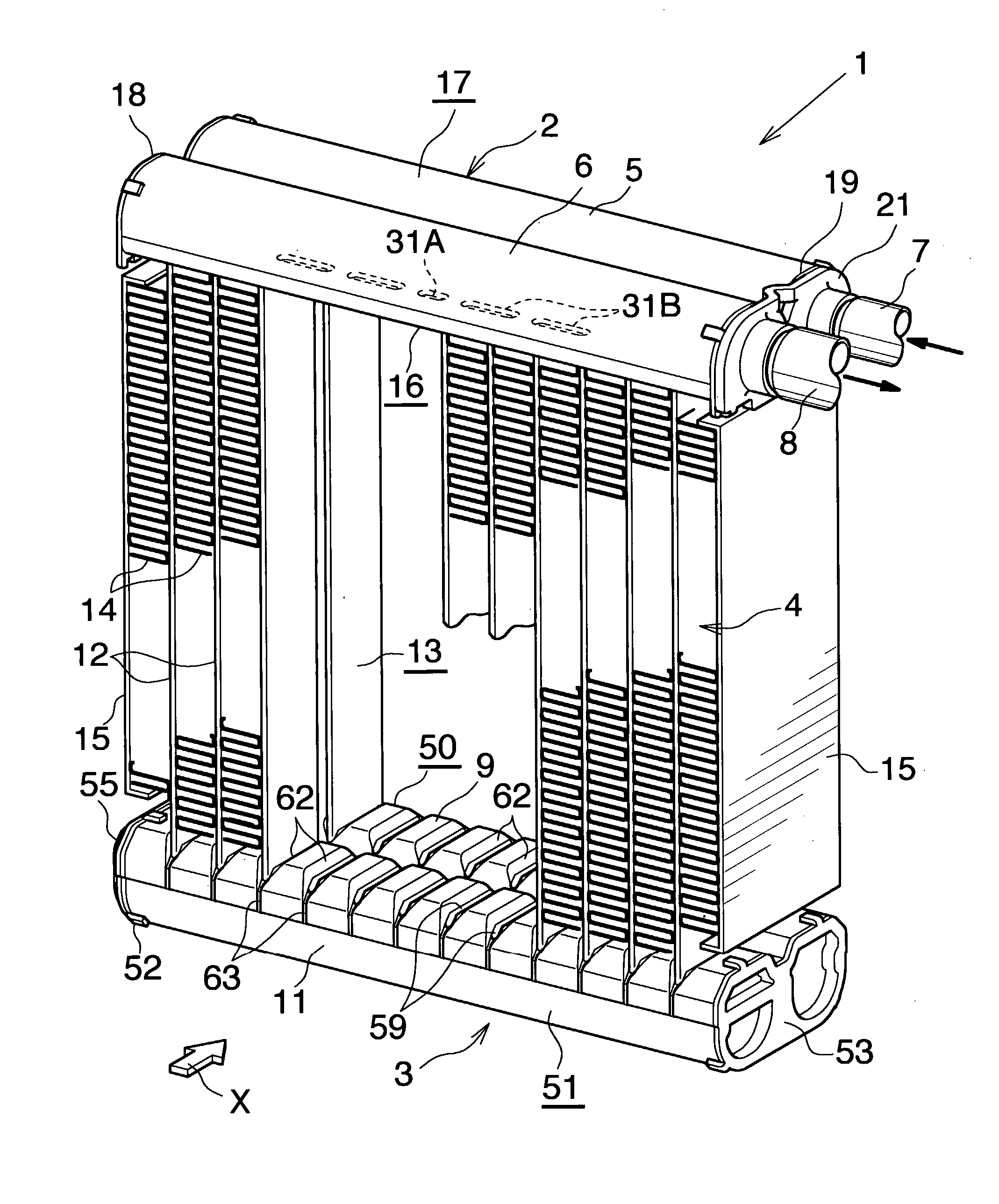
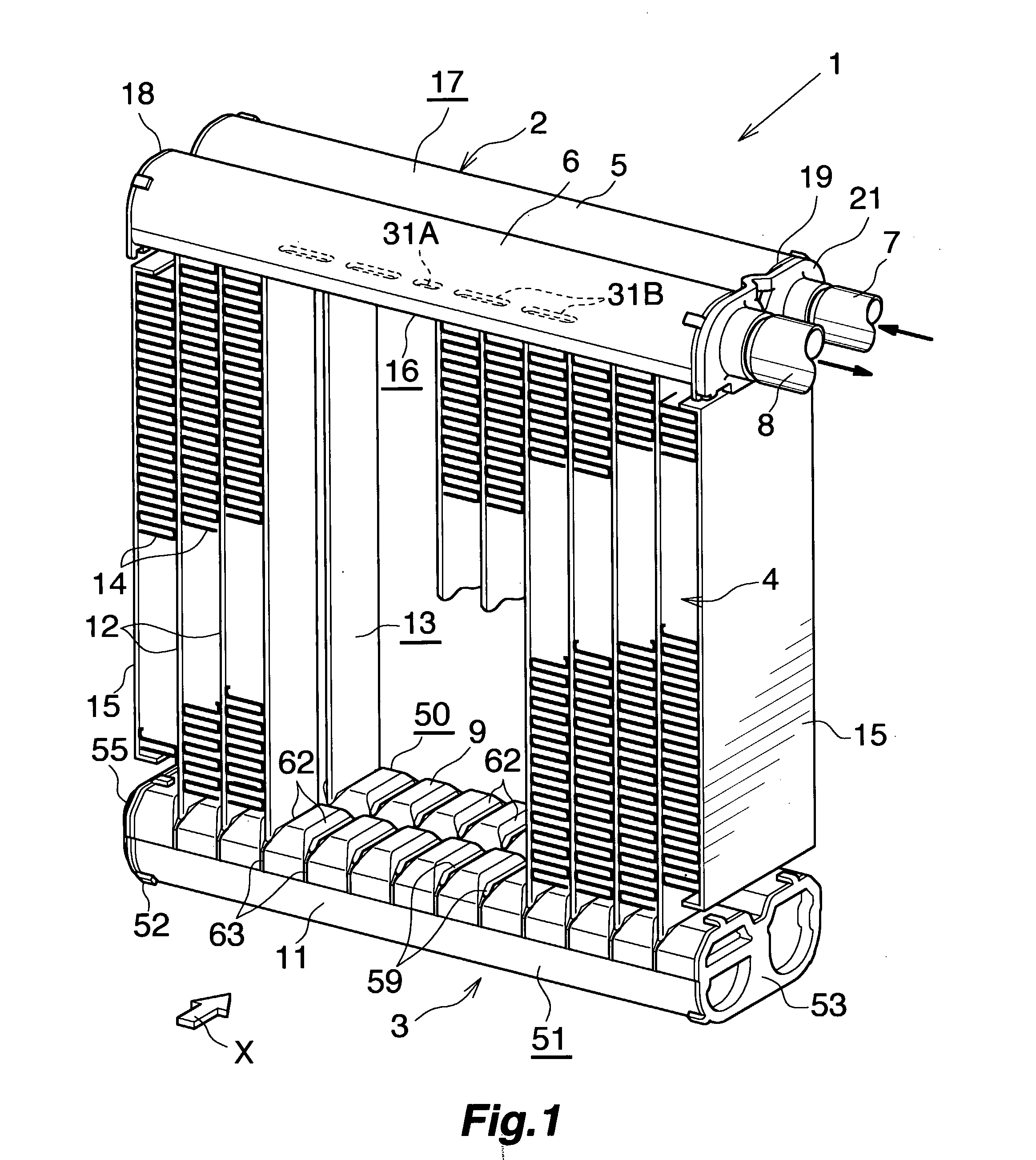
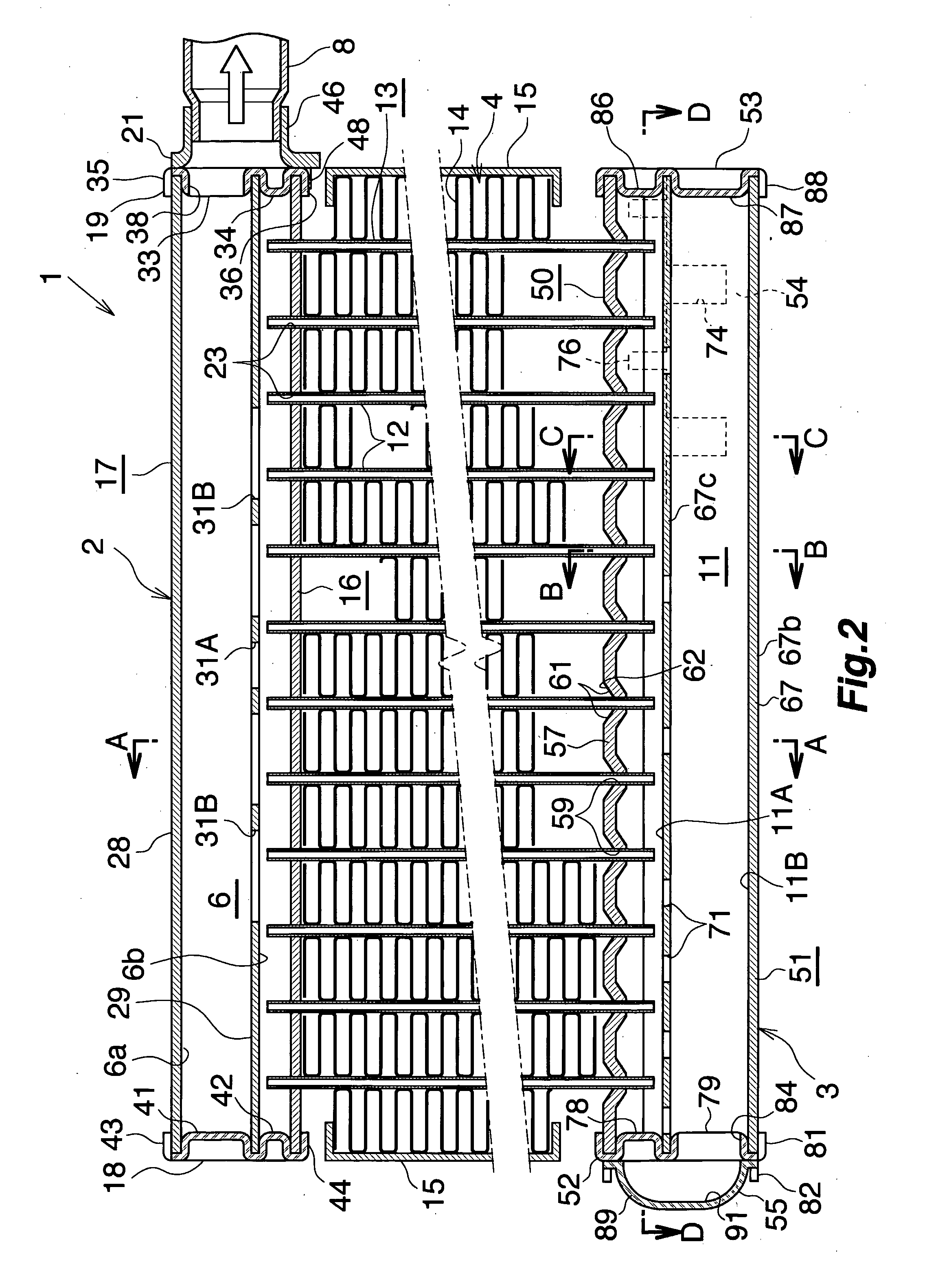
[0048] FIGS. 1 to 3 show the overall configuration of an evaporator, and FIGS. 4 to 10 show the configuration of essential portions of the evaporator. FIG. 11 shows how a refrigerant flows in the evaporator.

[0049] In FIGS. 1 to 3, the evaporator (1), which is used in a car air conditioner using a chlorofluorocarbon-based refrigerant, includes a refrigerant inlet / outlet tank (2) made of aluminum and a refrigerant turn tank (3) made of aluminum, the tanks (2) and (3) being vertically spaced apart from each other, and further includes a heat exchange core section (4) provided between the tanks (2) and (3).

[0050] The refrigerant inlet / outlet tank (2) includes a refrigerant inlet header section (5) located on a side toward the front (downstream side with respect to the air flow direction) and a refrigerant outlet header section (6) located on a side toward the rear (upstream side with respect to the air flow direction). A r...

embodiment 2

[0093] The present embodiment is illustrated in FIG. 12.

[0094] In the corrugate fins (14) of the evaporator of Embodiment 2, in addition to the cutouts (95) and the inward projections (96) provided at positions corresponding to clearances between the adjacent front and rear flat tubes (12), the cutouts (95) and the inward projections (96) are formed at front projecting portions (140) of the corrugate fins (14) projecting frontward beyond the front ends of the front flat tubes (12).

[0095] Other configurational features are similar to those of the evaporator (1) of Embodiment 1.

[0096] In the evaporator of Embodiment 2, when condensed water is generated on the surface of the corrugate fins (14), a portion of the condensed water flows downward through openings between the louvers (94). Also, the condensed water flows, by the effect of surface tension, toward joint portions between the flat tubes (12) and the wave crest portions (14a) and the wave trough portions (14b) of the corrugat...

embodiment 3

[0097] The present embodiment is illustrated in FIG. 13.

[0098] In the corrugate fins (14) of the evaporator of Embodiment 3, in place to the cutouts (95) and the inward projections (96) provided at positions corresponding to clearances between the adjacent front and rear flat tubes (12), the cutouts (95) and the inward projections (96) are formed at the front projecting portions (140) of the corrugate fins (14) projecting frontward beyond the front ends of the front flat tubes (12).

[0099] Other configurational features are similar to those of the evaporator (1) of Embodiment 1.

[0100] In the evaporator of Embodiment 3, when condensed water is generated on the surface of the corrugate fins (14), a portion of the condensed water flows downward through openings between the louvers (94). Also, the condensed water flows, by the effect of surface tension, toward joint portions between the flat tubes (12) and the wave crest portions (14a) and the wave trough portions (14b) of the corruga...


PUM


Abstract

A corrugate fin of an evaporator includes wave crest portions, wave trough portions, and flat connection portions connecting together the wave crest portions and the wave trough portions. Opposite end portions of a cutout extend to corresponding connection portions located at opposite ends of the wave crest portion and the wave trough portion. A projection projecting inward is formed integrally with end portions of the connection portions, the end portions of the connection portions corresponding to opposite ends of the cutout. The projection extends between the end portions of the connection portions located at the opposite ends of the wave crest portion and the wave trough portion. The projection projects inward in a shape resembling a lying letter V. The evaporator exhibits excellent drainage of condensed water and enables high work efficiency in manufacture thereof.

Description

CROSS REFERENCE TO RELATED APPLICATIONS [0001] This application is an application filed under 35 U.S.C. §111(a) claiming the benefit pursuant to 35 U.S.C. §119(e)(1) of the filing date of Provisional Application No. 60 / 619,009 filed Oct. 18, 2004 pursuant to 35 U.S.C. §111(b).TECHNICAL FIELD [0002] The present invention relates to an evaporator for use in a car air conditioner, which is a refrigeration cycle to be mounted on, for example, a vehicle. [0003] Herein and in the appended claims, the upper, lower, left-hand, and right-hand sides of FIGS. 1 and 2 will be referred to as “upper,”“lower,”“left,” and “right,” respectively. The downstream side of an air flow (a side represented by arrow X in FIG. 1, and a right-hand side in FIG. 3) is referred to as the “front,” and the opposite side as the “rear.”BACKGROUND ART [0004] A conventionally used evaporator for use in a car air conditioner includes a plurality of refrigerant flow members arranged in parallel, and corrugate fins each ...

Claims


Application Information

Patent Timeline
IPC IPC(8): F28D3/02
CPCF25B39/022F25B2500/01F28D1/05391F28F17/005F28F1/128F28F9/0214F28D2021/0085
Inventor HIGASHIYAMA, NAOHISATSURUMI, YUKIHIRO
Owner SHOWA DENKO KK
Why Eureka
Try Eureka