Power storage apparatus

a technology of power storage and power storage devices, which is applied in the direction of batteries, cell components, current conducting connections, etc., can solve the problems of difficult to sufficiently exert the battery performance of the entire assembled battery, difficult for the air to stay in the cooling space, etc., and achieve the effect of reducing temperature variation

Active Publication Date: 2017-06-20
TOYOTA JIDOSHA KK
View PDF17 Cites 0 Cited by
  • Summary
  • Abstract
  • Description
  • Claims
  • Application Information

AI Technical Summary

Benefits of technology

[0010]An object of the present invention, which has been made in order to solve the problems according to the conventional art, is to provide a power storage apparatus capable of accepting a cooling air flow in the power storage apparatus provided with spaces where cooling air is caused to flow, the spaces formed by alternately disposing spacers and power storage devices, and also capable of reducing variation in temperature among the plural power storage devices.
[0012]According to the present invention, it is possible to cause the air moving in the space due to the natural convection to stay in the space with guide members.
[0014]Hence, each spacer located in each end section of the power storage apparatus experiences deterioration of the cooling performance because of stagnation of the cooling air. However, each spacer located in each end section functions as an air insulating layer in a lower-temperature environment. Accordingly, it is possible to reduce thermal radiation of the power storage devices located in the end sections. In a lower-temperature environment, the temperature of the power storage devices located in the end sections of the power storage apparatus tends to become lower. Hence, according to the present invention, it is possible to reduce variation in temperature among the plural power storage devices.
[0016]In particular, the guide members downwardly guide the air having upwardly moved in the space due to the natural convection. Hence, air flows moving downward along opening surfaces of the respective openings located below the corresponding guide members are generated in the space. The air flows downwardly flowing along the opening surfaces of the openings function as air curtains to hinder the air flows moving toward the openings, thereby hindering the air from flowing out from the openings.
[0018]By providing the lower guide members, it is possible to block the air flows guided from above to below by the guide members so as not to flow out from the openings to the outside. Accordingly, it is possible to generate circulating flows including the air flows downwardly flowing along the opening surfaces of the openings, and thus the air is likely to stay in the space. The inner surface of each lower guide member is located more outward than the inner surface of the guide member; therefore, the air flow downwardly moving guided by the guide member is led to easily flow along the inner surface of the lower guide member, so that the air is likely to stay in the space.
[0020]The both ends of the flow passages opening toward the corresponding openings are located more inward than the corresponding openings in the right and left (lateral) direction; therefore, it is possible to hinder the air flows moving along the flow passages due to the natural convection from directly flowing out from the openings to the outside of the spacer. In addition, the guide members downwardly extend from the upper ends of the openings in a manner as to cover at least the openings of the flow passages located at the top end. The downward air flows generated by the guide members are caused in the upstream of the air flow moving due to the natural convection, thereby generating the air curtains to block the air flows moving toward the openings from the other flow passages located more downward than the flow passages located at the top end. Accordingly, the air moving in the space due to the natural convection becomes likely to stay in the space.

Problems solved by technology

Unfortunately, acceptance of a cooling air flow also causes the air in the cooling space to flow out to the outside from an inflow port or an outflow port of the cooling air provided to the cooling space, which makes it difficult for the air to stay in the cooling space.
If variation in temperature in the stacking direction among the plural battery cells becomes greater, it becomes difficult to sufficiently exert a battery performance of the entire assembled battery.

Method used


Image

  • Power storage apparatus
  • Power storage apparatus
  • Power storage apparatus

Examples


Embodiment Construction

[0028]An embodiment of the present invention will be described hereinafter.

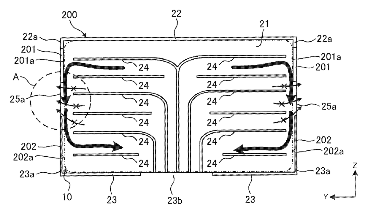
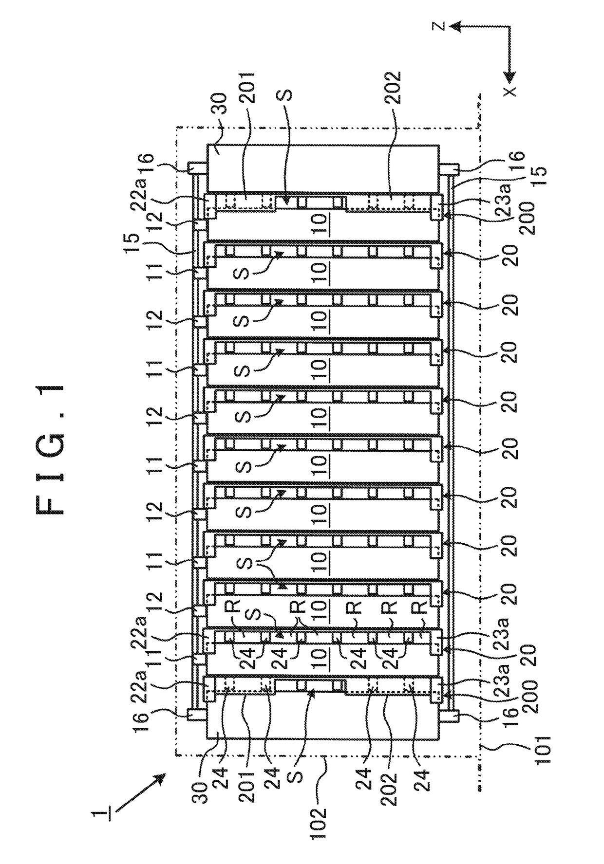
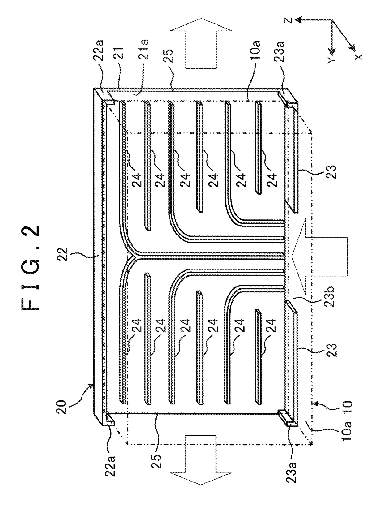
[0029]FIG. 1 to FIG. 5 are drawings showing Embodiment 1. FIG. 1 is a side view of an assembled battery 1 including a thermal regulating structure of the present embodiment. In FIG. 1 and other drawings, an X axis, a Y axis, and a Z axis orthogonally intersect one another. The relation of the X axis, the Y axis, and the Z axis is the same as that in the other drawings. In the present embodiment, an axis corresponding to a vertical direction is defined as the Z axis.

[0030]The assembled battery 1 of the present embodiment (an example of a power storage apparatus) is mounted to a vehicle as a power supply apparatus for supplying electric power to a drive motor. The vehicle herein may be a hybrid vehicle, an electric vehicle, or the like. A hybrid vehicle is equipped with another power source, such as a fuel cell and an internal combustion engine, as well as the assembled battery 1 as a power source to drive the ...


PUM

PropertyMeasurementUnit
circumferenceaaaaaaaaaa
structureaaaaaaaaaa
thermal radiationaaaaaaaaaa

Abstract

A power storage apparatus includes a plurality of spacers. The plurality of spacers is alternately stacked with the power storage devices. Each of the spacers defines a space through which cooling air flows. The spacers include first spacer and second spacer. The first spacer is a spacer disposed between the end plate and one of the plural power storage devices that is located adjacent to the end plate. The first spacer includes guide member. The guide member is arranged in a circumference of the opening of at least one of the inflow port and the outflow port so as to narrow the opening.

Description

INCORPORATION BY REFERENCE[0001]The disclosure of Japanese Patent Application No. 2014-222009 filed on Oct. 30, 2014 including the specification, drawings and abstract is incorporated herein by reference in its entirety.BACKGROUND OF THE INVENTION[0002]1. Field of the Invention[0003]The present invention relates to a structure of a power storage apparatus including a plurality of stacked power storage devices.[0004]2. Description of Related Art[0005]An assembled battery may be configured by stacking a plurality of battery cells, for example. In this case, there may be formed a cooling space for cooling air to cool the battery cells between every two adjacent battery cells disposed in the stacking direction.[0006]The assembled battery including the plurality of stacked battery cells has a higher thermal radiation in both end sections of the assembled battery than in a central section thereof in the stacking direction. For example, the battery cells located in the both end sections ar...

Claims


Application Information

Patent Timeline
Patent Type & Authority Patents(United States)
IPC IPC(8): H01M10/6566H01M10/647H01M10/613H01M10/625H01M2/10H01M10/6563H01M10/6557H01M50/209H01M50/291H01M50/50
CPCH01M10/6566H01M2/1077H01M10/613H01M10/625H01M10/647H01M10/6557H01M10/6563H01M2220/20H01M50/50H01M50/291H01M50/209Y02E60/10
Inventor HIROE, YOSHIHIKO
Owner TOYOTA JIDOSHA KK
Why Eureka
Try Eureka