Surface flow diverting and static charging ducted pores on wing or blade tip to reduce wake and BVI noise

a surface flow and static charging technology, applied in the direction of all-wing aircraft, boundary layer controls, influencers by generating vortices, etc., can solve the problem that the technology state does not offer a simple method to produce counter-rotating vortices without, and achieve the effect of promoting the interlayer movement of air molecules

Inactive Publication Date: 2007-11-01
PAL ANADISH KUMAR
View PDF7 Cites 49 Cited by
  • Summary
  • Abstract
  • Description
  • Claims
  • Application Information

AI Technical Summary

Benefits of technology

[0008]Selective use of triboelectric materials and/or coatings inside the ducts and on the wing surfaces is done to static charge the air rubbing against fast moving ducts and wing surfaces. The constant presence of suspended particles in air, impart a static charge on it, when they rub against appropriate triboelectric materials; consequently, triboelectric materials also get static charge. A static-charged triboelectric surface or lining on the wing first attracts air and as soon as the air receives the ch

Problems solved by technology

U.S. Pat. No. 6,948,906 does not disclose the implications of variations in locating the inlet either on the chord plane or between the chord plane and the upper surface of the rotorcraft airfoi

Method used


Image

  • Surface flow diverting and static charging ducted pores on wing or blade tip to reduce wake and BVI noise
  • Surface flow diverting and static charging ducted pores on wing or blade tip to reduce wake and BVI noise
  • Surface flow diverting and static charging ducted pores on wing or blade tip to reduce wake and BVI noise

Examples


Embodiment Construction

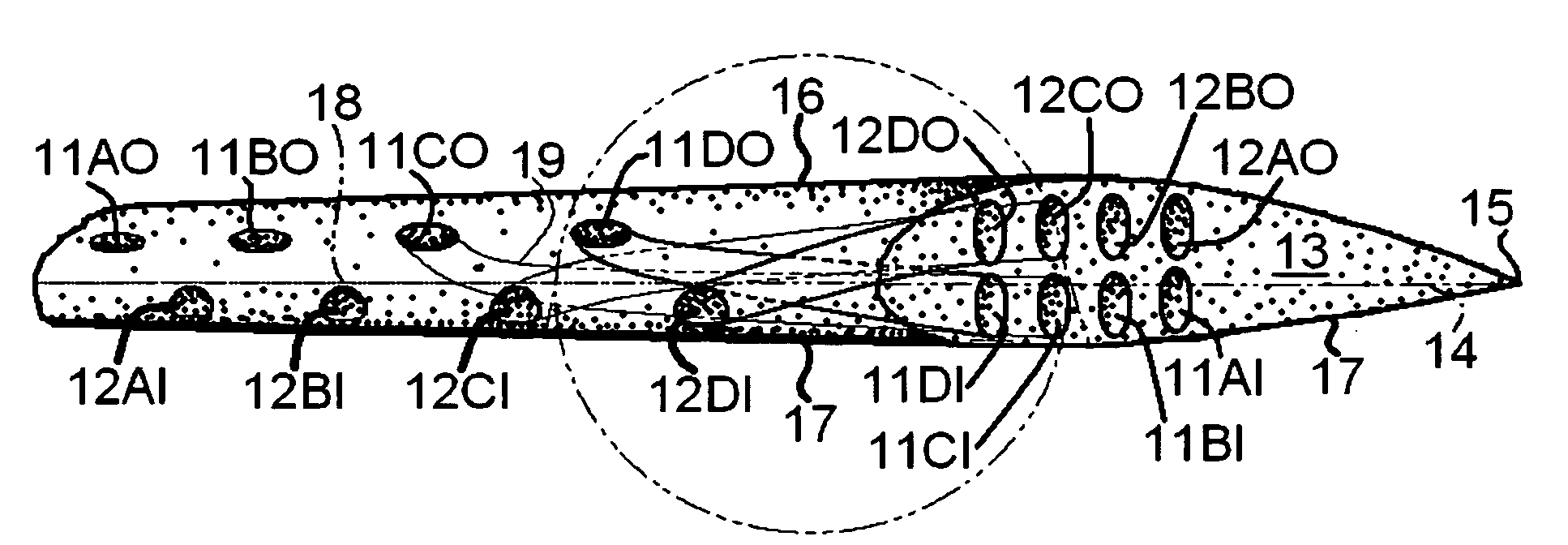
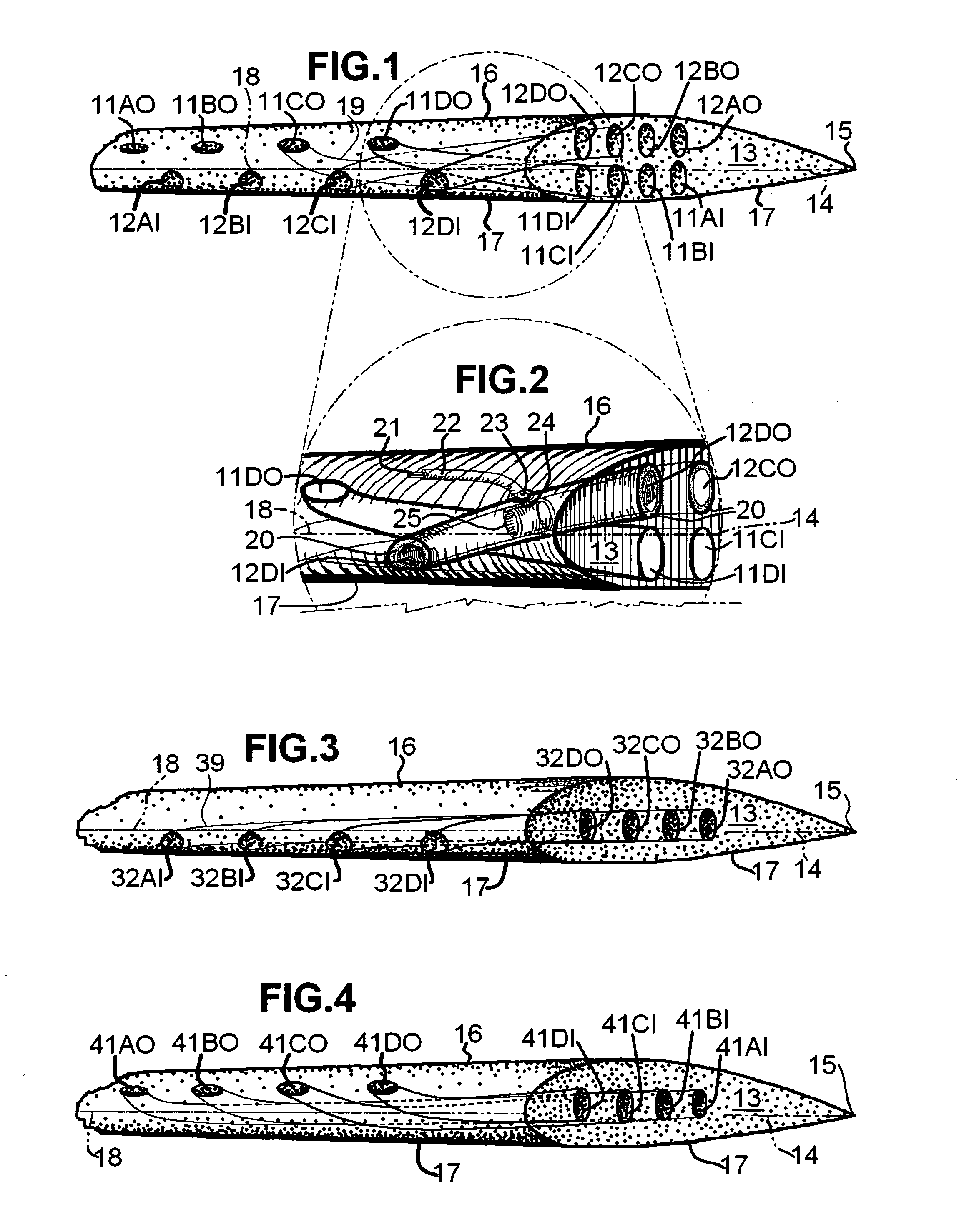
[0027]The airfoil wing tip ends shown in FIG. 1, FIG. 3 and FIG. 4 could belong to an aircraft or rotorcraft. The wing tip end in FIG. 1 has airfoil section NACA 2415 with upper surface 16, lower surface 17, leading edge 18, chord line 14, trailing edge 15 and wing tip side face 13. FIG. 2 also shows the above-recited elements save trailing edge 15. Wing tip side face 13 acts as a span-wise closing, if the airfoil described above is considered to have an inside volume formed by the enclosure of upper surface 16, lower surface 17 and wing tip side face 13. In FIG. 1, 11AI, 11BI, 11CI and 11DI are wing tip side face inlets to ducted pores (one shown as ducted pore 19 in FIG. 1) which correspondingly lead air adjacent to wing tip side face 13 to upper surface outlets 11AO, 11BO. 11CO and 11DO on upper surface 16 (FIG. 1). Similarly, Lower surface inlets 12AI, 12BI, 12CI and 12DI on lower surface 17 (FIG. 1) are airfoil lower surface inlets to ducted pores (similar to ducted pore 19 in ...


PUM


Abstract

Air pressure distribution for airfoil lower and upper surfaces is utilized to divert airflow using ducts formed in space-curve shapes placed inside the airfoil volume, through span-wise located inlets from high pressure areas on the airfoil lower surface near the leading edge and through chord-wise spaced inlets on the side face of the airfoil wing tip correspondingly to the side face of the airfoil wing tip through chord-wise spaced outlets on the side face of the airfoil wing tip and to span-wise located outlets to the low pressure areas on the airfoil upper surface. Triboelectric materials on the wing surfaces are employed to static charge the air in drag. Inside the ducts, the employment of either triboelectric linings and materials, or HV-supplied electrodes, or both, help to static charge the diverted air flow to and from the airfoil wing tip side face to diffuse wing tip vortex core early.

Description

CROSS-REFERENCE TO RELATED APPLICATIONS [0001]Foreign application priority claimed from Indian Patent Application No. 1091 / DEL / 2006 of Apr. 28, 2006, entitled, ‘Surface flow diverting and static charging ducted pores on wing or blade tip to reduce wake and BVI noise.’STATEMENT REGARDING FEDERALLY SPONSORED RESEARCH OR DEVELOPMENT[0002]Not ApplicableREFERENCE TO A MICROFICHE APPENDIX[0003]Not ApplicableBACKGROUND OF THE INVENTION[0004]This invention relates to reduction of aircraft wing wake and rotorcraft blade-vortex-interference.[0005]In a rotorcraft airfoil, the concept of leading edge incident flow diversion to wing tip was proposed by Dancila in 2002. U.S. Pat. No. 6,948,906 (Leishman, et al) discloses a scheme of having at least one inlet located above the leading edge of a rotorcraft airfoil blade, where the leading edge incident air flow entering an arc-shaped tube through the inlet located above the leading edge and comes out as a jet from an outlet located at the blade tip...

Claims


Application Information

Patent Timeline
IPC IPC(8): B64C3/14
CPCB64C27/001B64C27/467Y10S415/914B64C2230/12B64C2230/28Y02T50/166Y02T50/10
Inventor PAL, ANADISH KUMAR
Owner PAL ANADISH KUMAR
Why Eureka
Try Eureka