IC tag housing case

Inactive Publication Date: 2007-11-01
FUJITSU LTD
View PDF29 Cites 27 Cited by
  • Summary
  • Abstract
  • Description
  • Claims
  • Application Information

AI Technical Summary

Benefits of technology

[0012] A more specific objective of the present invention is to provide an IC tag housing case that allows for exchanging information accurately between the IC tag and the reader / writer without increasing costs for the IC tag.
[0041] The present invention provides an advantage in that information is accurately exchanged between the IC tag and the IC tag reader / writer, without increasing costs for the IC tag.

Problems solved by technology

However, in this case, the high magnetic permeability material has to be provided on every IC tag 15, which causes a problem of increased costs for the IC tag.

Method used


Image

  • IC tag housing case
  • IC tag housing case
  • IC tag housing case

Examples


first embodiment

A First Embodiment

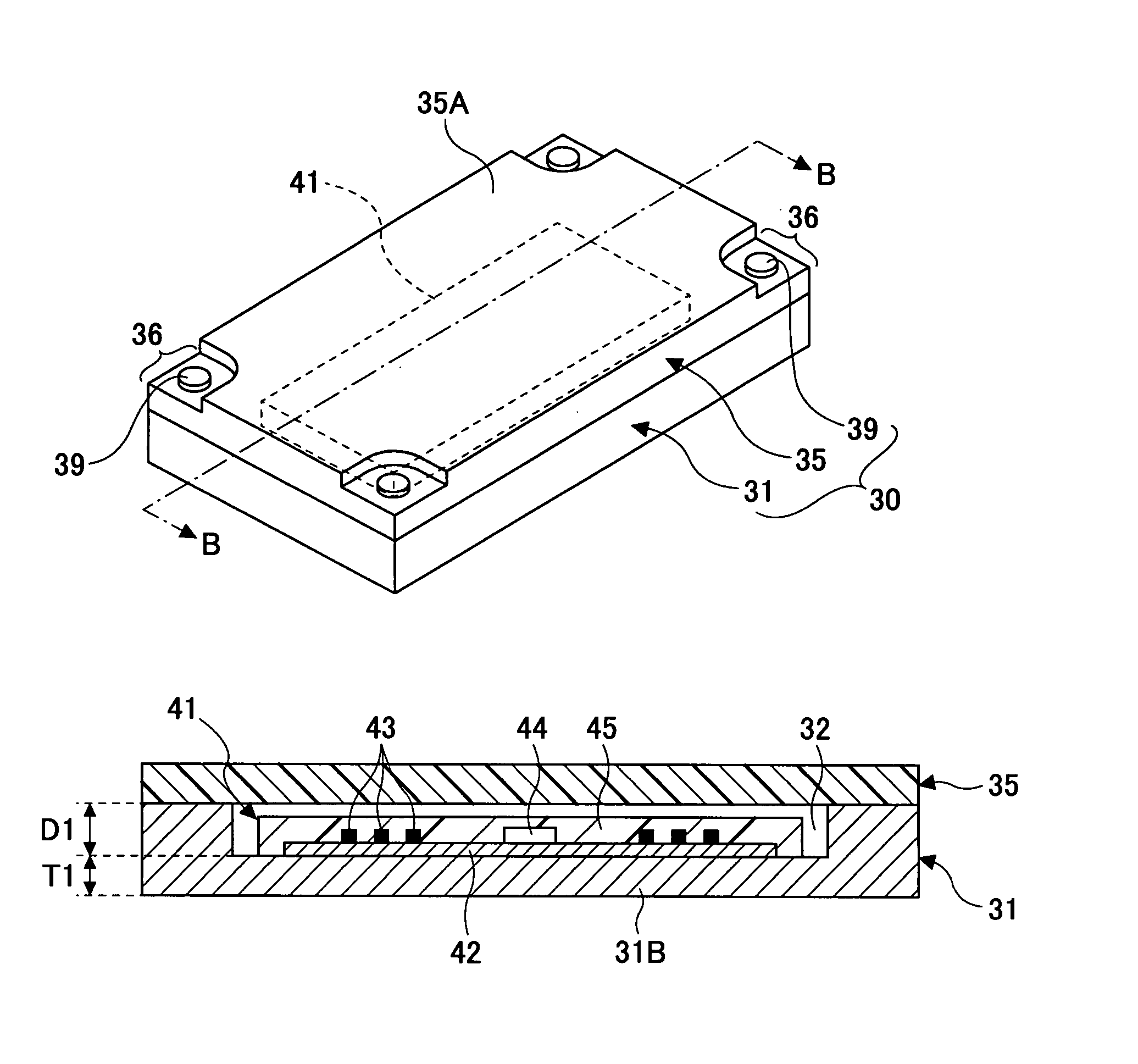
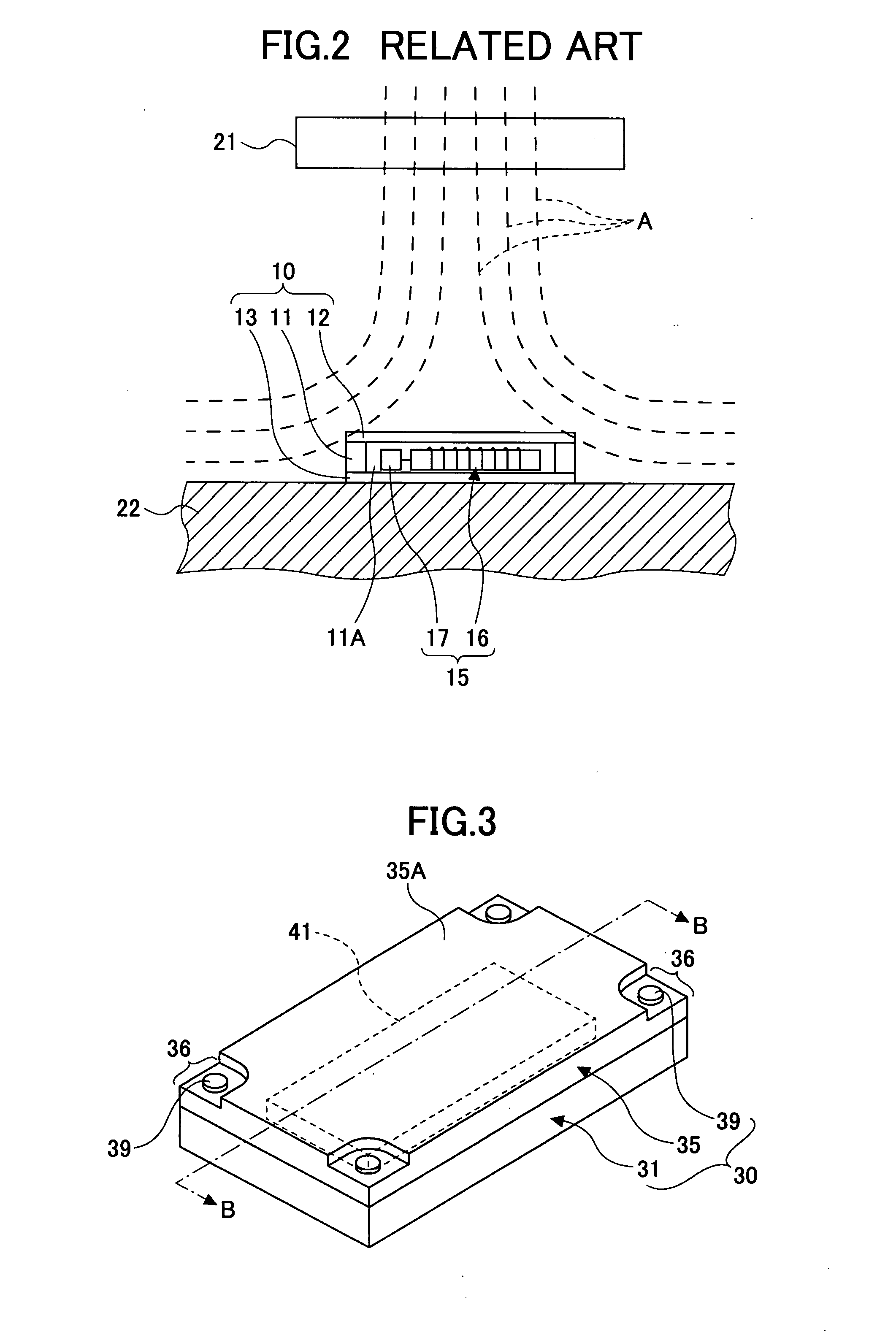
[0061] Referring to FIGS. 3 through 5, an IC tag housing case 30 as a first embodiment of the present invention will be described. FIG. 3 is a perspective view of the IC tag housing case according to the first embodiment, where an IC tag is housed; FIG. 4 is a cross-sectional view taken along a B-B line of a structure (the IC tag and the IC tag housing case) shown in FIG. 3. FIG. 5 is an exploded perspective view of the structure shown in FIG. 3. It is noted here in FIG. 4 that T1 represents a thickness of a bottom plate portion 31B of a case body (referred to as “thickness T1”, hereinafter), and D1 represents a depth of a space portion 32 (referred to as “depth D1”, hereinafter).

[0062] The IC tag housing case 30, while housing the IC tag 41 therein, is attached on an object 48 such as a product and a physical body (referred to as an “object”, hereinafter) whose information is to be managed. The IC tag housing case 30 is generally composed of a lid body 35 that re...

second embodiment

A Second Embodiment

[0080] Referring to FIGS. 8 through 10, an IC housing case 60 according to a second embodiment of the present invention will be described. FIG. 8 is a perspective view of the IC tag housing case according to the second embodiment of the present invention, where an IC tag is housed; FIG. 9 is a cross-sectional view taken along an E-E line of a structure (the IC tag and the IC tag housing case) shown in FIG. 8. FIG. 10 is an exploded perspective view of the structure shown in FIG. 8. It is noted here in FIGS. 8 and 9 that T2 represents the thickness of a frame body 61 (referred to as “thickness T2”, hereinafter), and T3 represents the thickness of a bottom plate 62 (referred to as “thickness T3”, hereinafter). Additionally, in FIGS. 8 through 10, the same symbols are given to the same constituting portions as those in the structure (the IC tag 41 and the IC tag housing case 30) shown in FIG. 3.

[0081] The IC tag housing case 60, while housing the IC tag 41 therein, ...

third embodiment

A Third Embodiment

[0086] Referring to FIGS. 11 through 13, there will be described an IC tag housing case 70 according to a third embodiment of the present invention. FIG. 11 is a perspective view of the IC tag housing case, according to the third embodiment, in which an IC tag is housed; FIG. 12 is a cross-sectional view taken along an F-F line of a structure (the IC tag and the IC tag housing case) shown in FIG. 11. FIG. 13 is an exploded perspective view of the structure shown in FIG. 11. It is noted here in FIG. 12 that D2 represents the depth of a space portion 72 (referred to as “depth D2”, hereinafter), and T4 is the thickness of a bottom plate portion 71A of a case body 71 (referred to as “thickness T4”, hereinafter), and T5 represents the thickness of a high magnetic permeability member 73 (referred to as “thickness T5”, hereinafter). Additionally, in FIGS. 11 through 13, the same symbols are given to the same constituting portions as those in the structure (the IC tag 41 a...


PUM


Abstract

The present invention relates to an IC tag housing case configured to house an IC tag therein, and the objective thereof is to accurately exchange information between an IC tag and a reader / writer without increasing costs for an IC tag. To this end, an IC tag housing case is configured to include a lid body formed of a material that allows electromagnetic waves to pass therethrough, and a case body having a space portion where an IC tag is housed and formed of a high magnetic permeability material.

Description

CROSS-REFERENCE TO RELATED APPLICATION [0001] This application is a U.S. continuation application filed under 35 U.S.C. 111 (a) claiming benefit under 35 U.S.C. 120 and 365(c) of PCT application JP2005 / 000200, filed Jan. 11, 2005. The foregoing application is hereby incorporated herein by reference.BACKGROUND OF THE INVENTION [0002] 1. Field of the Invention [0003] The present invention relates to an IC tag housing case that houses an IC tag. [0004] 2. Description of the Related Art [0005] Currently, it is being carried out in order to improve business efficiency that an IC tag (also known as an RFID tag) is attached on a product, a physical object, or the like (referred to as simply an “object”, hereinafter) subjected to information management by a computer thereby to read the information from the IC tag via a reader / writer. The IC tag (shipping tag) stores ID (identification information) in a small IC chip, and exchanges (writes or reads) information through radiowaves between the...

Claims


Application Information

Patent Timeline
IPC IPC(8): G08B13/14H01L23/02
CPCG06K7/10178G06K19/07771G06K19/04G06K19/005
Inventor FURUTANI, NAGAHISA
Owner FUJITSU LTD
Why Eureka
Try Eureka