
Display Control System

Active Publication Date: 2007-11-01
APTIV TECH LTD
View PDF99 Cites 185 Cited by
  • Summary
  • Abstract
  • Description
  • Claims
  • Application Information

AI Technical Summary

Benefits of technology

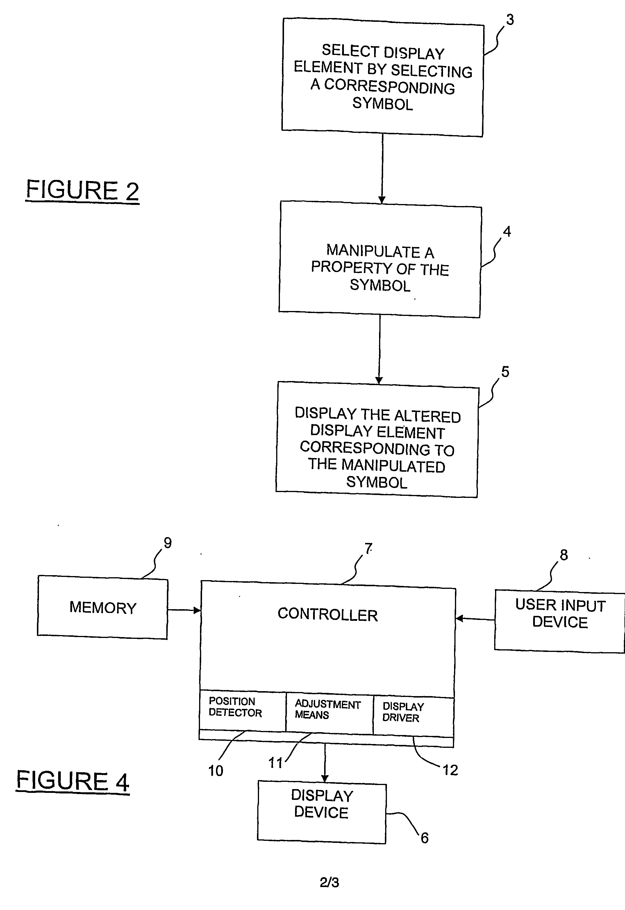
[0020] iii) displaying the first and second display elements on their respective display layers in their adjusted position or positions or with their adjusted visual property or properties in order to improve the ability of a user of the multi-layer display system to view the overlapping or potentially overlapping portion of the first and / or second display element.
[0109] The present invention may allow a user to nest, organise and in general terms present specific components of display content depending on their own preferences and preferably in the best possible configuration for data analysis or information absorption purposes.

Problems solved by technology

However, in an MLD unit, because images on all but the rearmost display layer are at least partially transparent, overlapping of display elements can lead to viewing difficulties.
In some circumstances, this can make it virtually impossible for a user to correctly or comfortably view the foreground display element.
This technology is in its infancy and although the aforementioned problem of a dark or opaque rear display element reducing the available light for an overlapped front display element is reduced or eliminated, there is still a problem in that the appearance of overlapping portions of display elements in different layers can interfere, thereby reducing the legibility or discernability of the information displayed (where legibility relates to the distinctness that makes perception or reading easy).
An example of the aforementioned problem occurs when two display elements such as GUI windows, both displaying text, are positioned over each other (that is, they overlap) in separate display layers of a multi-layer display device.
The result is that the text on both layers is very difficult (if not impossible) to read.
Overlaying text on a graphic image (or vice versa) can have the same effect of rendering the text difficult to read.
More specifically, the problem is at its worst: when there is very little contrast (that is, difference in colour, pattern, brightness etc) between the overlapped display elements or images displayed on different display layers, and / or when at least one display layer is displaying cluttered information.

Method used


Image

  • Display Control System
  • Display Control System
  • Display Control System

Examples


Embodiment Construction

Adjustment of Visual Properties and / or Location of Display Elements to Improve Viewing Experience

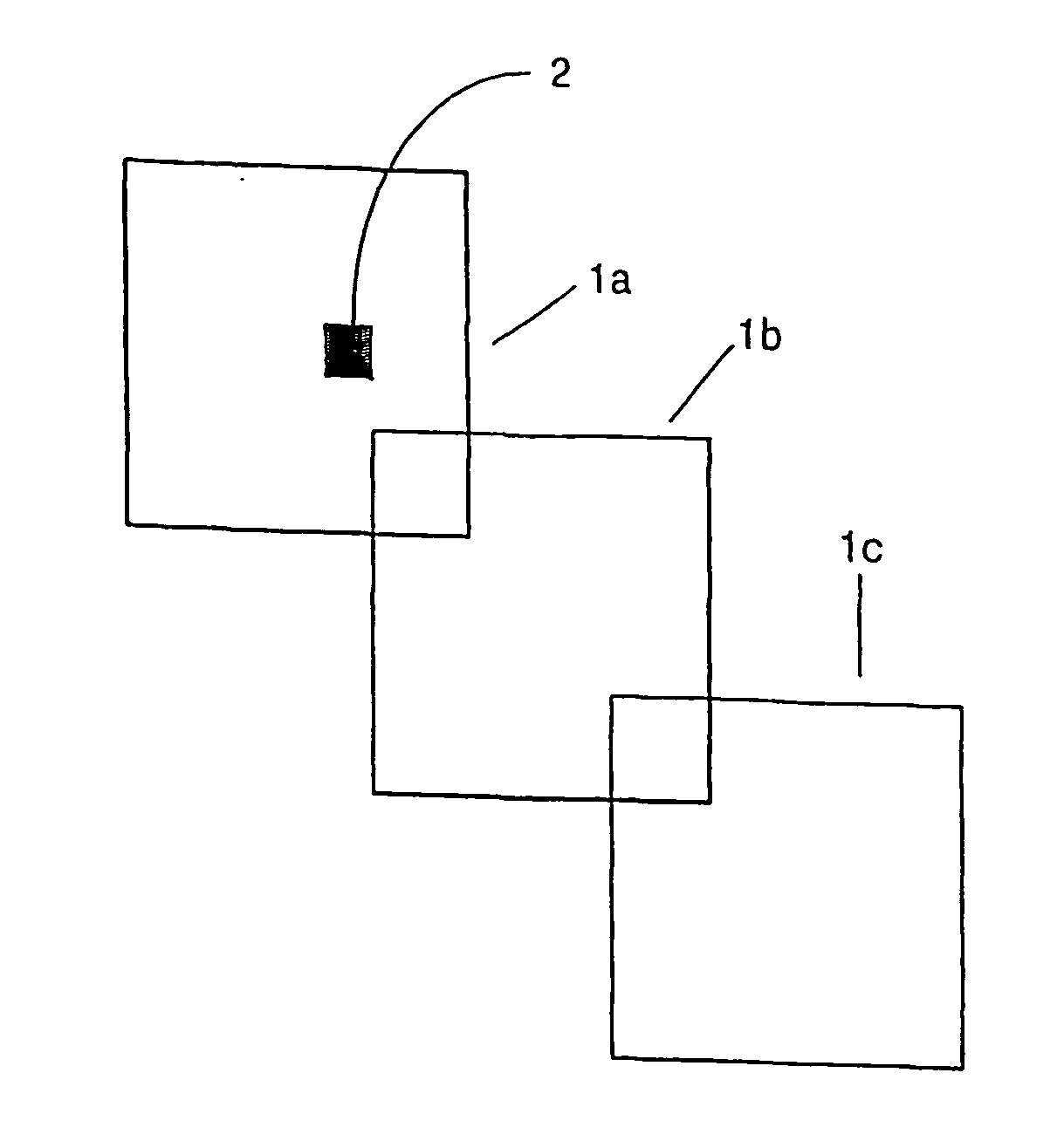
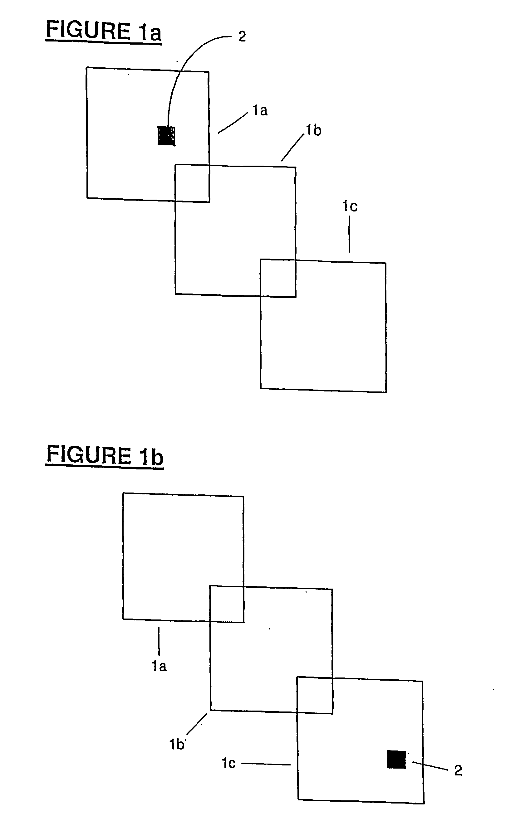
[0116]FIGS. 1a &1b illustrate a block schematic diagram of the display layers of a single multi-layer display device prior to and after the transfer of a display element between display layers of the display using the present invention. Each display layer may comprise a LCD display layer which is selectively transparent with the ability to display images thereon.

[0117] In the instance shown, a series of display layers 1a, 1b, 1c are arranged and displaced in a line with respect to one another, however, in use, each of the layers are aligned, one directly in front of the next to form a stacked or sandwiched construction. A single display element, shown in this embodiment as a graphical user interface window 2 is presented on the front layer 1a in the initial situation shown with respect to FIG. 1a. Conversely, after a transfer made in conjunction with the present invention, the same di...


PUM


Abstract

A display control system for a multi-layer display system including at least one multi-layer display unit (6). A multi-layer display unit includes multiple stacked or overlapped display layers (1a, 1b, 1c, 14, 15) each adapted to render display elements (2, 16B, 17B, 18B) thereon for viewing through the uppermost display layer. The level of difficulty for a user to view an overlapped image differs depending on the colour, brightness or type of images (for example text-on-text) being displayed and also the layer in which the image is being displayed and whether the image is currently active. At least any overlapping portion of display elements from different display layers are adjusted (automatically or by a user) in order to improve the viewing experience for a viewer. Types of adjustment possible include moving the images within their display layer or to an alternative display layer or altering their visual properties (such as colour, brightness, contrast etc).

Description

TECHNICAL FIELD [0001] This invention relates to a display control system and more particularly though not solely to a method and apparatus for simplifying the operation of and / or improving a user's viewing experience with a multi-layer display system (a display system consisting of one multi-layer display (MLD) device, multiple interconnected MLD devices, or interconnected single layer display (SLD) devices and / or MLD devices). BACKGROUND ART [0002] Multi-layered displays provide a significant improvement over existing single layer displays (SLD) or screens. MLD units may be used to nest display content over spacially displaced or stacked or sandwiched layers to provide an enhanced mechanism for information absorption and analysis by users. An example of an existing multi-layer display is discussed for example in WO9942889A in which each layer may be, for example, a selectively transparent Liquid Crystal Display (LCD) layer having the ability to display images of adjustable transpa...

Claims


Application Information

Patent Timeline
IPC IPC(8): G09G3/36G02B27/22G06F3/14G06T11/00G09G5/14H04N13/395
CPCG09G3/36G09G5/14G06F3/048G09G2340/10H04N13/0495G09G2300/023H04N13/395G09G3/20
Inventor ENGEL, GABRIEL DAMONFERGUSON, DAVID JOHNMACLEOD, HARNISH JOHN OGILVIESEYMOUR, BRUCE DAVID
Owner APTIV TECH LTD
Learn More