
Fixture

a technology of fixing and fixing rods, applied in the field of lighting, can solve the problems of large decorative effect or the ability to upgrade to future lamp technology of various lengths or quantities, large expense, and inconvenience, and achieve the effect of reducing and increasing the cost of maintenan

Inactive Publication Date: 2007-11-01
MEDICAL ILLUMINATION INT INC
View PDF10 Cites 65 Cited by
  • Summary
  • Abstract
  • Description
  • Claims
  • Application Information

AI Technical Summary

Benefits of technology

[0052] The housing is equipped with various removable perforated slots allowing the fixture the ability to use various lamp lengths, lamp types and lamp quantities without having to purchase or use a new housing. All the necessary / required parts, such as end plates and lamp holders, are removable and reconfigurable in the field or in the manufacturing facility to allow various lamp and other necessary light needs to be preformed. The housing is an apparatus that assembles without the use of specialty tools. In addition to providing light reflectivity, the additional functions of the housing apparatus is to provide the flexibility to configure the light fixture in any desired configuration with respect to the number of lamps, the length of lamps, the wattage of lamps and any other relevant parameter associated with the configuration of the light fixture.
[0073] The Shadow Box™ trim can be removed and attached to the light fixture without tools or attachment mechanisms. One Shadow Box™ trim is easily interchanged with another Shadow Box™ trim. The Shadow Box™ trim provides decorative trim which can be made of various materials, colors, textures, designs and other characteristics. The Shadow Box™ trim can be manufactured with corporate logos or other branding or advertising designs and is not limited to corporate designs. For example, graphic designs, images of animals, equipment, directions, and the like can be adapted for use with the Shadow Box™ trim. The Shadow Box™ trim can be rotated and laid into place so as to be removed and replaced without being lifted above the T-grid.

Problems solved by technology

Such direct form of fluorescent lighting is relatively inexpensive, but very plain and utilitarian, without much decorative effect or the ability to upgrade to future lamp technologies of various lengths or quantities and without consideration for simplifying the related maintenance issues associated with the normal operations of a florescent lighting fixture.
Such installations are generally custom designed and installed, with attendant, generally extensive, expense.

Method used


Image

  • Fixture
  • Fixture
  • Fixture

Examples


Embodiment Construction

[0134] The above general description and the following detailed description are merely illustrative of the generic invention, and additional modes, advantages, and particulars of this invention will be readily suggested to those skilled in the art without departing from the spirit and scope of the invention.

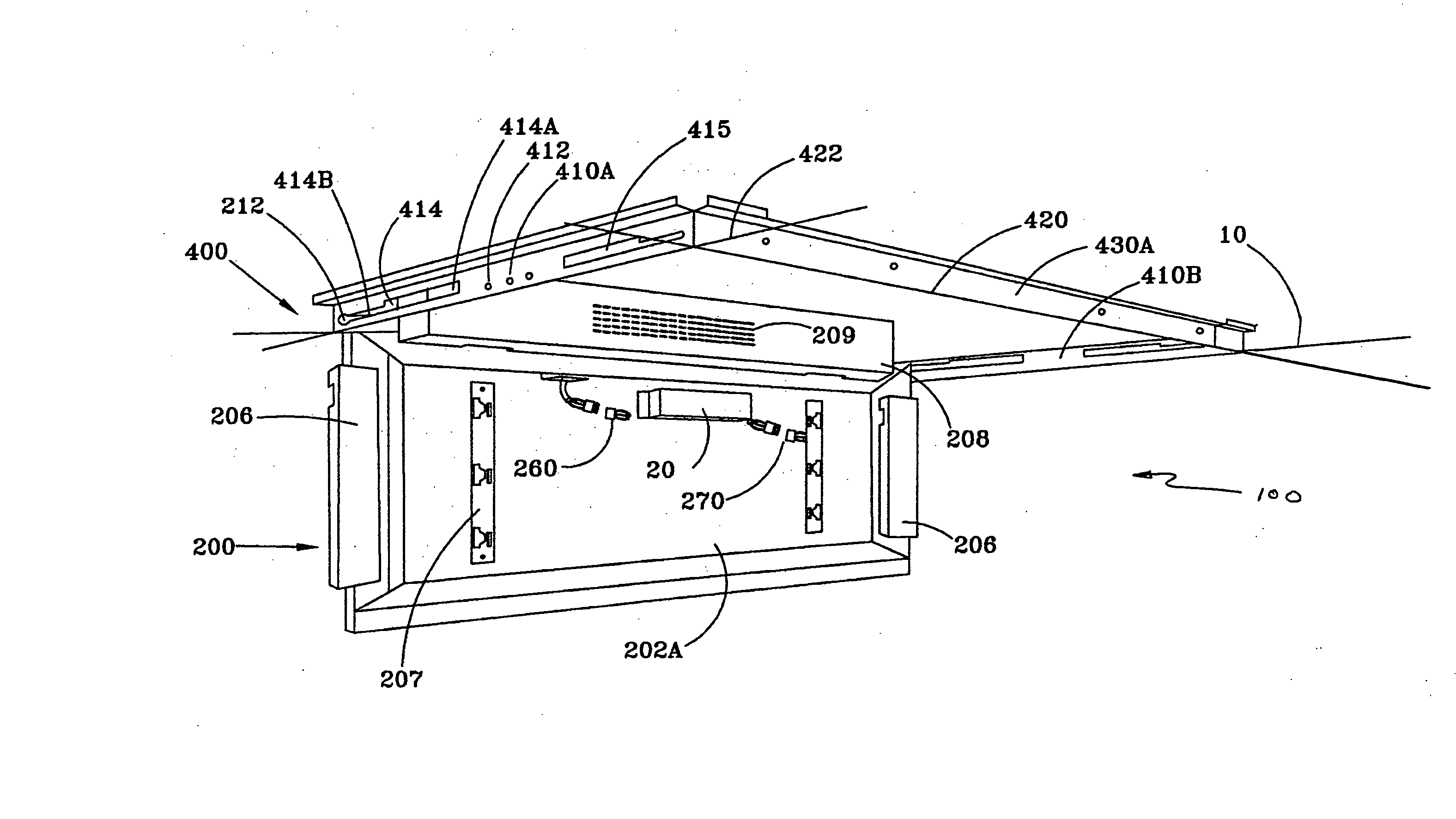
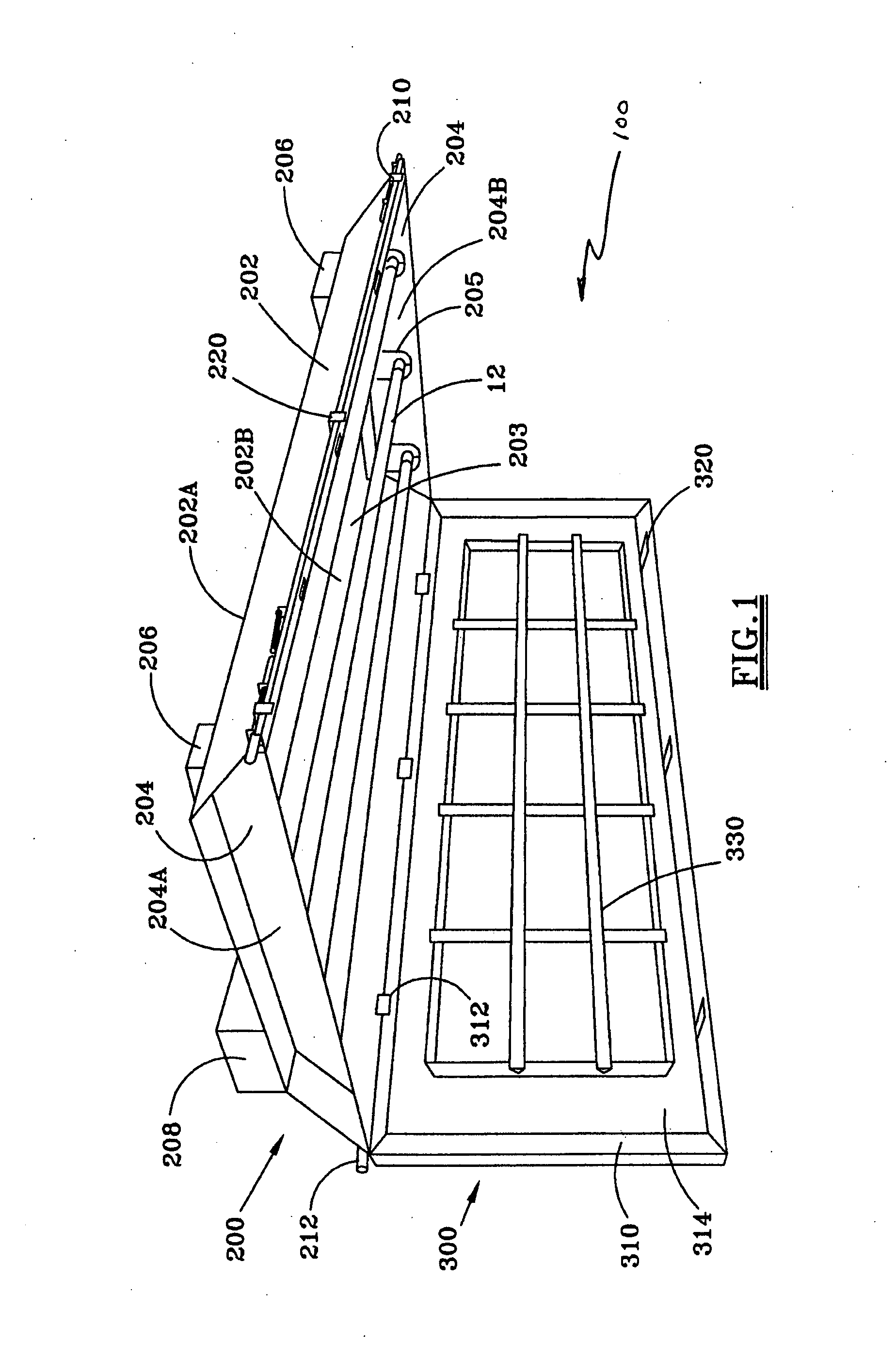
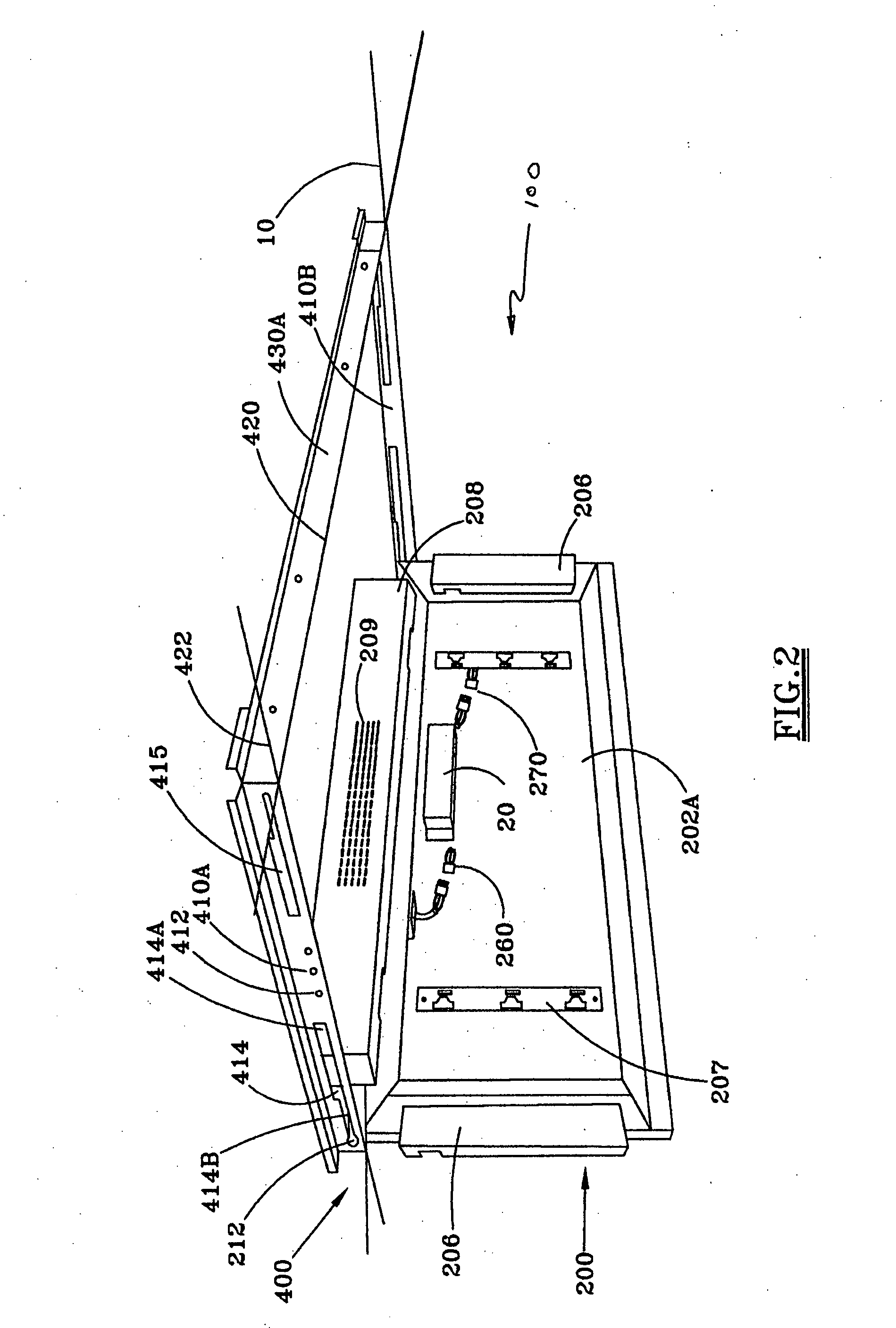
[0135]FIG. 1 is a perspective view of a preferred embodiment of the light fixture apparatus 100 of the present invention with the Shadow Box™ trim 300 pivoted from and disposed at a 90 degree angle to the fixture / troffer 200. The fixture / troffer 200 and the Shadow Box™ trim 300 have a detachable relationship as well as a pivoting relationship. Thus, the Shadow Box™ trim 300 can either be removed completely from the fixture / troffer 200, or the Shadow Box™ trim 300 can be in a pivoting relationship with the fixture / troffer 200.

[0136] The fixture / troffer 200 comprises a base 202, end plates 204, lamp holder covers 206, a ballast cover 208, a fixture release mechanism 210 and a piv...


PUM

PropertyMeasurementUnit
Efficiencyaaaaaaaaaa

Abstract

The present invention relates generally to the field of lighting. More particularly, the present invention relates to decorative, reconfigurable or energy and maintenance efficient fluorescent light fixtures that use energy efficient lamps and ballasts, and to an apparatus for new fluorescent light fixtures and for replacing an existing fluorescent light fixture for energy efficient use. Further, the present invention relates to a system that integrates light fixtures with a suspended grid ceiling or a solid ceiling.

Description

CROSS REFERENCE TO RELATED APPLICATION [0001] The present application is a continuation-in-part application of the application of Mark Welker, U.S. Ser. No. 11 / 031,928, filed Jan. 8, 2005, entitled FIXTURE AND METHODS.FIELD OF THE INVENTION [0002] The present invention relates generally to the field of lighting. More particularly, the present invention relates to decorative, reconfigurable or energy and maintenance efficient fluorescent light fixtures, and to an apparatus for new fluorescent light fixtures and for replacing an existing fluorescent light fixture for energy efficient use. Further, the present invention relates to a system that integrates light fixtures with a suspended grid ceiling or a solid ceiling. BACKGROUND OF THE INVENTION [0003] Typically in buildings, suspended ceilings having a metallic grid that supports panels in grid openings are common. Generally, in such ceilings, direct lighting fixtures replace panels in selected grid openings to provide room illuminat...

Claims


Application Information

Patent Timeline
IPC IPC(8): F21V29/00
CPCF21S8/02F21V17/107F21V17/18F21V21/04Y10T29/49826F21W2111/06F21Y2103/00Y02B20/386F21V23/026F21V23/008Y02B20/30
Inventor WELKER, MARK L.
Owner MEDICAL ILLUMINATION INT INC
Learn More