
Encoding and/or decoding system, medium, and method with spatial prediction and spatial prediction compensation of image data

a technology of image data and encoding, applied in the field of encoding and/or decoding of image data, can solve the problems of delay in encoding and decoding, inability to perform real-time spatial prediction and encoding, and inability to use the pixel values of blocks on the left of the current block to perform encoding and decoding, so as to prevent error diffusion

Active Publication Date: 2007-11-01
SAMSUNG ELECTRONICS CO LTD
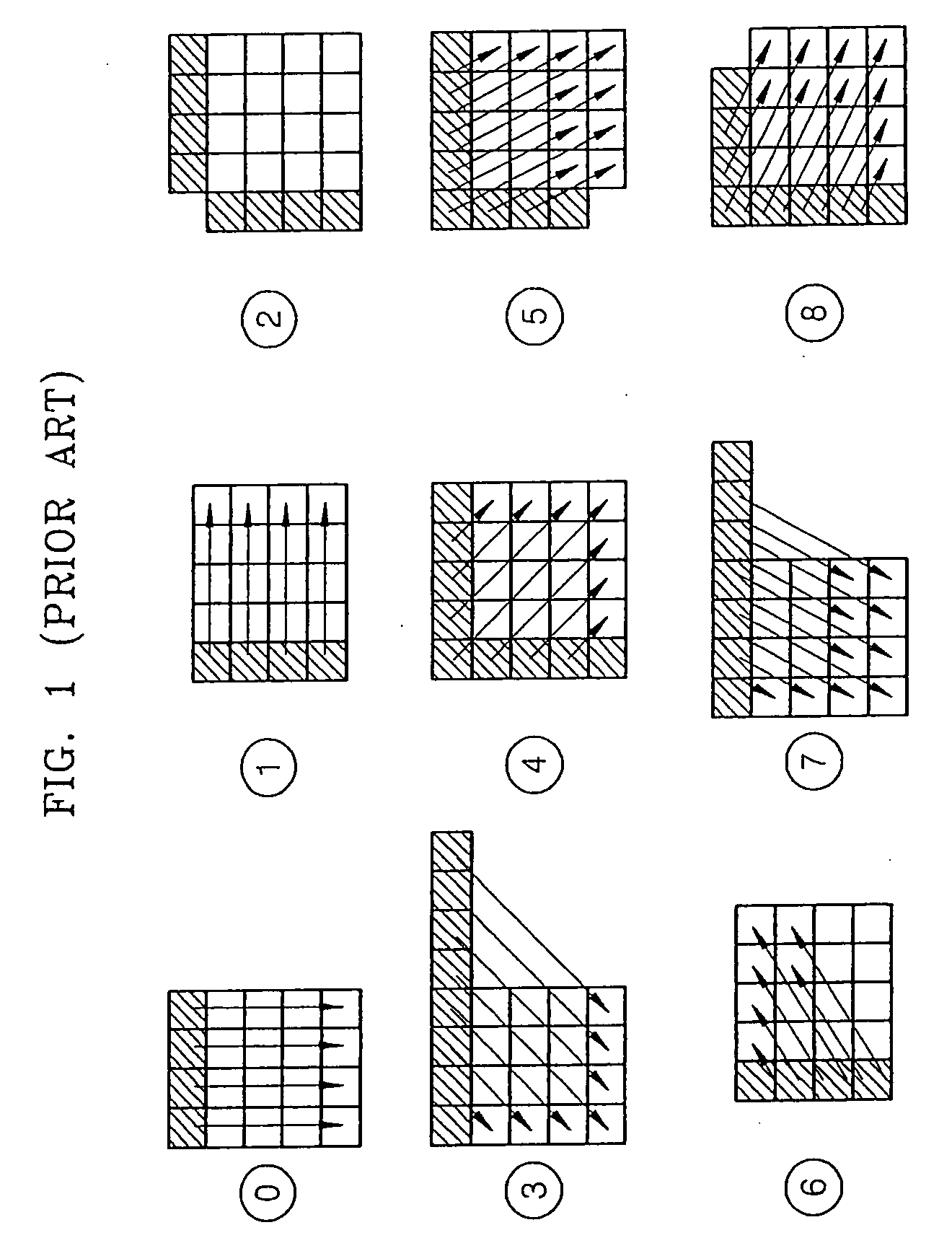
View PDF6 Cites 73 Cited by
  • Summary
  • Abstract
  • Description
  • Claims
  • Application Information

AI Technical Summary

Benefits of technology

[0010] One or more embodiments of the present invention provide a system, medium, and method for spatial prediction of image data, to achieve real time encoding and prevent error diffusion.
[0011] One or more embodiments of the present invention also provide a system, medium, and method with encoding image data, to achieve real time encoding and prevent error diffusion.
[0012] One or more embodiments of the present invention also provide a system, medium, and method with spatial prediction compensation of image data, to make it possible to perform real time prediction compensation on image data that is encoded in real time.
[0013] One or more embodiments of the present invention also provides a system, medium, and method decoding image data, to make it possible to perform real time decoding on image data that is encoded in real time.

Problems solved by technology

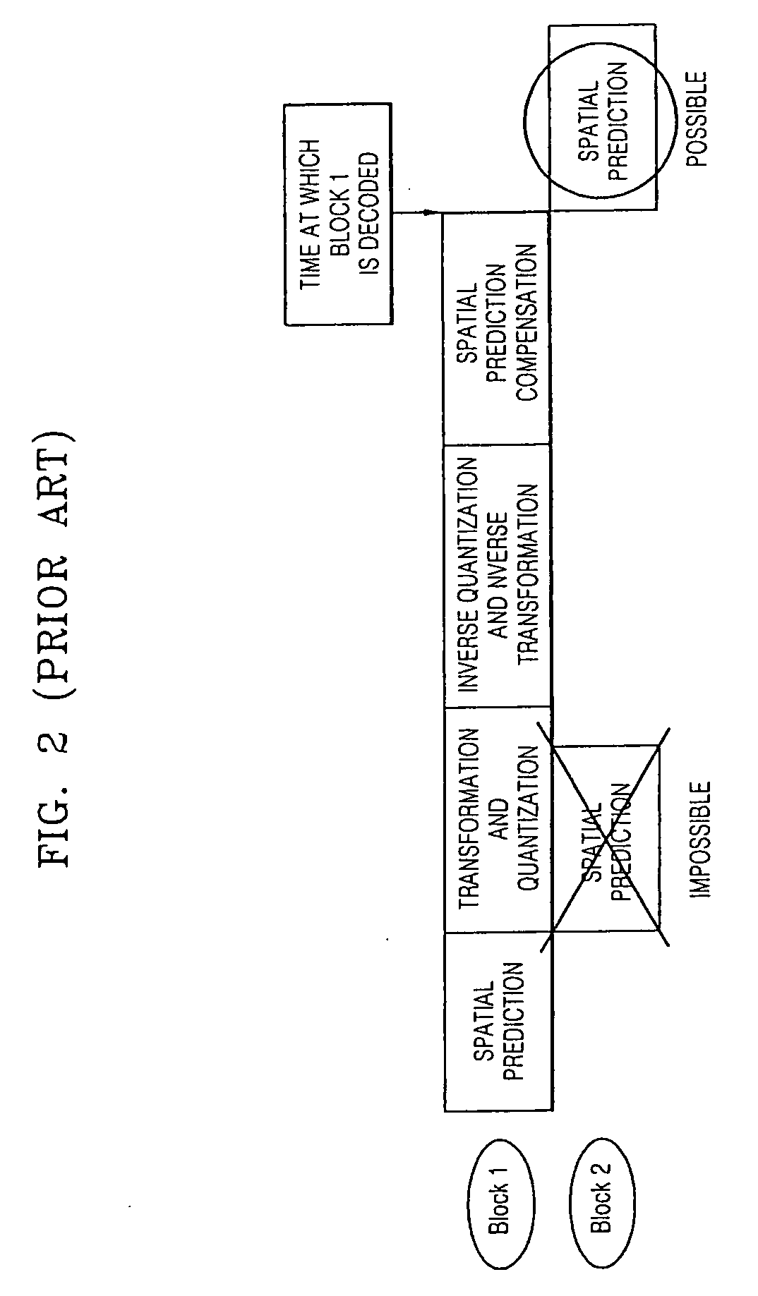
However, since the conventional spatial prediction is performed using pixel values of blocks on the left of the current block, it becomes impossible to perform real time spatial prediction and encoding.
Thus, such conventional spatial processing can not be performed using pixel values of blocks on the left of the current block.
Such a pipeline processing failure results in similar failures of a real time encoding and decoding of image data, resulting in encoding and decoding delays.
Moreover, if an error is generated during the spatial prediction of an image having edges, the spatial prediction will be performed based on the error, causing error diffusion and display quality degradation.

Method used


Image

  • Encoding and/or decoding system, medium, and method with spatial prediction and spatial prediction compensation of image data
  • Encoding and/or decoding system, medium, and method with spatial prediction and spatial prediction compensation of image data
  • Encoding and/or decoding system, medium, and method with spatial prediction and spatial prediction compensation of image data

Examples


Embodiment Construction

[0042] Reference will now be made in detail to embodiments of the present invention, examples of which are illustrated in the accompanying drawings, wherein like reference numerals refer to the like elements throughout. Embodiments are described below to explain the present invention by referring to the figures.

[0043]FIG. 3 illustrates a system for spatial prediction of image data, according to an embodiment of the present invention. Referring to FIG. 3, the system may include a pixel value filtering unit 100, a prediction mode determination unit 120, and a spatial prediction unit 140, for example.

[0044] The pixel value filtering unit 100 may filter pixel values of neighboring blocks in a row immediately above a current block, which can be used for spatial prediction of the current block, among neighboring blocks that are spatially adjacent to the current block, and output the filtered pixel values to the prediction mode determination unit 120, for example. The filtering is desire...


PUM


Abstract

An encoding and / or decoding system, medium, and method with spatial prediction and spatial prediction compensation. The system may include a spatial prediction unit that spatially predicts pixel values of a current block of an image using neighboring blocks in a row immediately above the current block among neighboring blocks that are spatially adjacent to the current block. The spatial prediction unit performs spatial prediction using replaced pixel values of neighboring blocks in a row immediately above the current block every predetermined row unit, with the pixel values of neighboring blocks in a row immediately above the current block every predetermined row unit being replaced with a predetermined reference value.

Description

CROSS-REFERENCE TO RELATED APPLICATIONS [0001] This application claims the benefit of Korean Patent Application No. 10-2006-0033582, filed on Apr. 13, 2006, in the Korean Intellectual Property Office, the disclosure of which is incorporated herein in its entirety by reference. BACKGROUND OF THE INVENTION [0002] 1. Field of the Invention [0003] One or more embodiments of the present invention relate to encoding and / or decoding of image data, and more particularly, to an encoding and / or decoding system, medium, and method with spatial prediction and spatial prediction compensation. [0004] 2. Description of the Related Art [0005] Conventionally, spatial prediction is required to encode image data. For example, intra spatial predictive encoding is a technique for predicting pixel values of a current block using spatial correlation of an image. To be more specific, the pixel values of the current block are predicted using a differential value of decoded pixel values of blocks that are ad...

Claims


Application Information

Patent Timeline
Patent Type & Authority Applications(United States)
IPC IPC(8): H04N7/12H04N11/04H04N19/50H04N1/41H04N19/11H04N19/12H04N19/134H04N19/136H04N19/14H04N19/196H04N19/436H04N19/593H04N19/60H04N19/61H04N19/625H04N19/80
CPCH04N19/176H04N19/61H04N19/85H04N19/11H04N19/80H04N19/593H04N19/124H04N19/59H04N19/82
Inventor LEE, SANG-JOKIM, WOO-SHIKLEE, SI-HWAKIM, DO HYUNG
Owner SAMSUNG ELECTRONICS CO LTD
Learn More