
Hanger with strap retainer

Inactive Publication Date: 2007-11-08
RICHARDSON DANIELLE
View PDF20 Cites 1 Cited by
  • Summary
  • Abstract
  • Description
  • Claims
  • Application Information

AI Technical Summary

Benefits of technology

[0009] It is an object of the present invention to provide an improved hanger suitable for hanging garments with straps. It is also an object of the present invention to provide a hanger suitable for hanging strapped garments next to other strapped garments with reduced possibility of adjacent garments becoming entangled. Further, it is an object of the present invention to provide such a hanger, which is easy to manufacture and use.
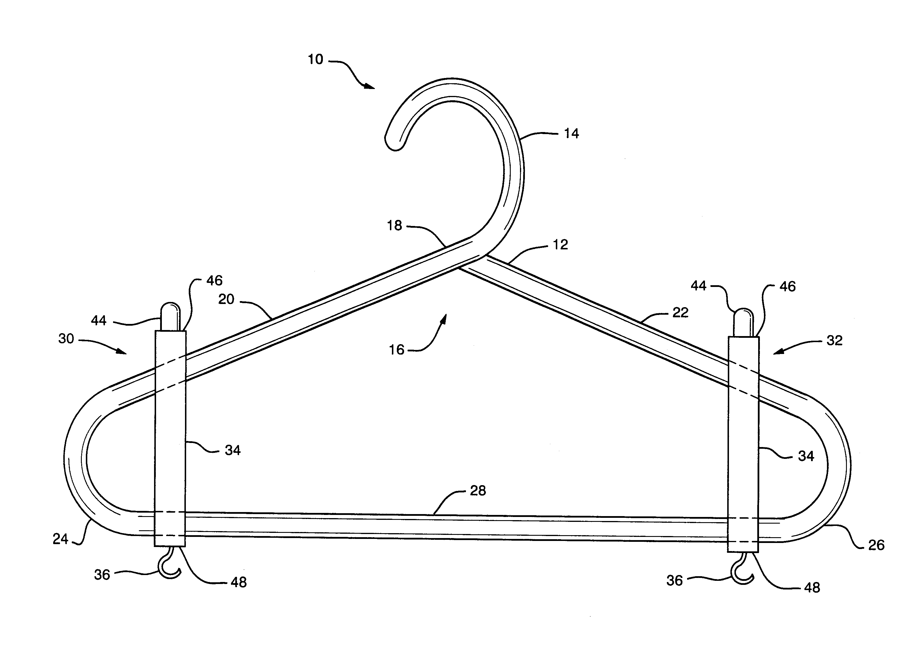
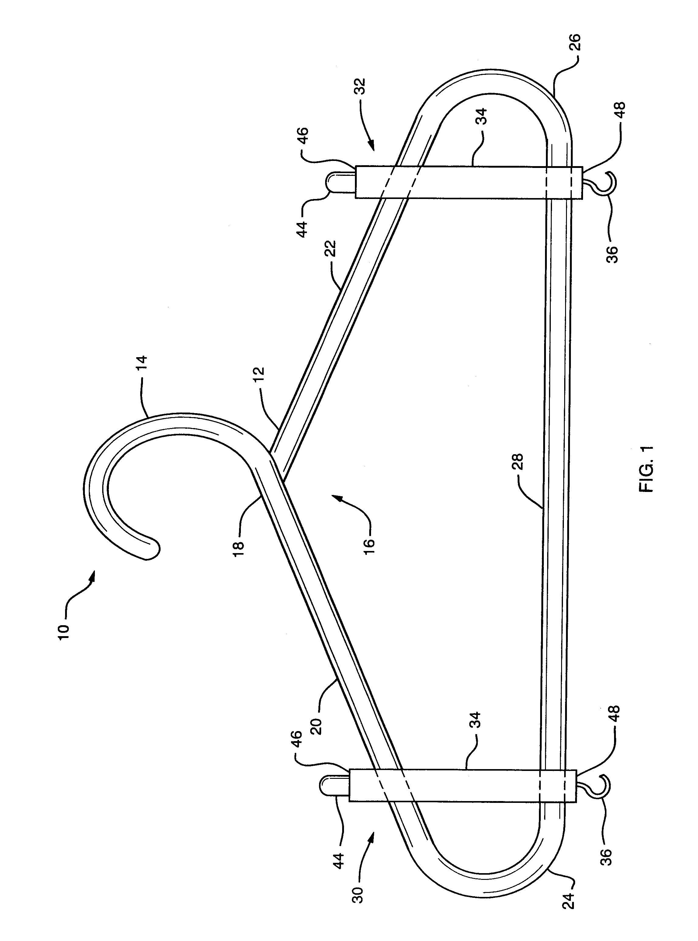
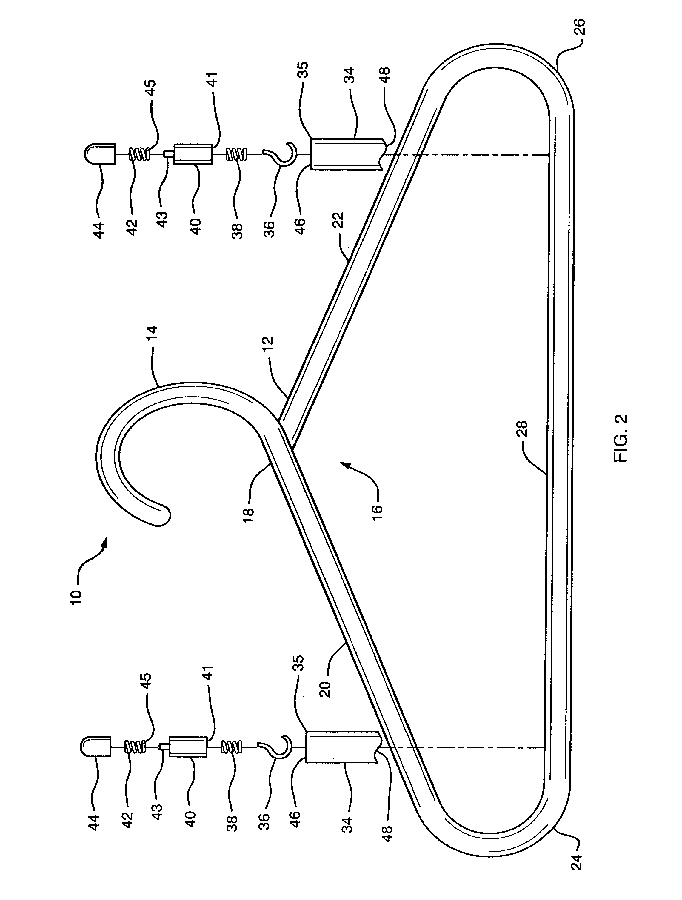
[0011] Each of the strap retaining components is a spring-loaded device positioned substantially entirely in a housing. The spring-loaded device includes a strap hook at one end and an actuator at the opposing end. The strap hook is arranged to be retracted within the housing when the strap of a garment is being hanged or has been removed from the hanger. The application of pressure to the actuator forces the strap hook out of the housing such that the strap may be removed therefrom or placed thereon. The spring-loaded device allows for protraction and retraction of the strap hook with respect to the housing.
[0012] This arrangement of the strap retaining component ensures that only the garment or garments with straps to be applied to a particular hanger can be retained by that hanger. Since the strap hook is only exposed for the purpose of applying or removing the straps of the garment(s) of interest when application or removal is desired, it cannot hook the straps of other garments. Garments will not become entangled with the hangers of adjacent garments. This arrangement eliminates the difficulty for the consumer of removing from a rack or replacing on a rack a garment of interest. It also improves the appearance of the garment display and reduces the retailer's need to expend time to maintain the display. In addition, the retaining component may easily be applied to an existing type of hanger.

Problems solved by technology

Since the strap hook is only exposed for the purpose of applying or removing the straps of the garment(s) of interest when application or removal is desired, it cannot hook the straps of other garments.

Method used


Image

  • Hanger with strap retainer
  • Hanger with strap retainer
  • Hanger with strap retainer

Examples


Embodiment Construction

[0018] A strap-retaining hanger 10 of the present invention is shown in FIGS. 1 and 2. The strap-retaining hanger 10 includes a conventional hanger 12 having a hook 14 and a main body 16. The hook 14 is arranged to hang the hanger 10 on a support structure, such as a retail store rack. The hook 14 and the main body 16 are joined at interface 18. The conventional hanger 12 may be formed as a single integral device or in sections joined together. The main body 16 includes a first extended wing 20 and a second extended wing 22. The first extended wing 20 and the second extended wing 22 extend downwardly at an angle from the interface 18. The hanger 12 may be of the type shown in the drawings, in which the first extended wing 20 and the second extended wing 22 are joined together at ends 24 and 26 thereof by joining section 28. Alternatively, the hanger 12 may be of the type having only the first extended wing 20 and the second extended wing 22 without the two joined together. Further, ...


PUM


Abstract

A strap-retaining hanger for hanging garments with straps such that the garments do not become entangled with adjacent garments and / or hangers. The strap-retaining hanger includes a main hanger body and one or more strap-retaining components. Each strap-retaining component includes a housing attached to the main body of the hanger. The housing retains therein a strap hook joined to a spring member. An actuator is used to place the spring member in compression to cause protraction of the strap hook out of the housing. When pressure is released from the actuator, the spring compression is released and the strap hook retracted into the housing. The strap hooks hold the straps of the garment and are only exposed when there is a desire to put the garment on the hanger or to take it off the hanger.

Description

BACKGROUND OF THE INVENTION [0001] 1. Field of the Invention [0002] The present invention relates to hangers. More particularly, the present invention relates to hangers for hanging garments with straps. Still more particularly, the present invention relates to hangers modified to include one or more strap retainers to hang garments with thin straps including, for example, dresses. [0003] 2. Description of the Prior Art [0004] A hanger is a device used to hold a garment in a manner that allows a person to observe the entirety of the garment. There are many forms of hangers available commercially. They vary based on the type of garment to be displayed. However, in most instances, the hanger includes a main body on which the garment hangs, and a hook for placement of the hanger on a rod or other type of support structure. The hook extends from the main body, which includes one or more outwardly extending wings. Many such hangers angle the outwardly extending wings to maintain the shap...

Claims


Application Information

Patent Timeline
IPC IPC(8): A41D27/22
CPCA47G25/50
Inventor RICHARDSON, DANIELLE
Owner RICHARDSON DANIELLE
Learn More