Lighted lens housing for jewelers loupe

a technology for jewelers loupes and lenses, applied in the field of lenses, can solve the problems of affecting the quality of jewelers loupes, affecting the appearance of jewelers loupes, etc., and achieves the effect of reducing the number of lenses, avoiding the formation of a hazard, and avoiding the formation of hazard clouds

Inactive Publication Date: 2007-11-08
DUHE JERRY
View PDF2 Cites 22 Cited by
  • Summary
  • Abstract
  • Description
  • Claims
  • Application Information

AI Technical Summary

Benefits of technology

[0010] A further object of the present invention is to provide an extremely lightweight lens housing, illumination means and power source to work in conjunction with the typical jeweler's loupe and not adversely affect its ability to be held in place.
[0011] Still another object of the present invention is to reduce, if not eliminate dark spots and shadows concerning the objects being viewed and to address all areas available through the lens with illumination.
[0012] And still another object of the present invention is for its manufacture to be cost effective and to easily attach to a typical jewelers loupe while accepting a desired lens.

Problems solved by technology

Illumination in conjunction with magnification has always been an issue since the inception of the magnification lens.
This of course is very limited because a large part of the viewing area goes un-addressed.
Those hands free visors, which are illuminated, normally have a light source in the center of the visor or at the corners, which again leave a substantial portion of the viewing area un-addressed.

Method used


Image

  • Lighted lens housing for jewelers loupe
  • Lighted lens housing for jewelers loupe
  • Lighted lens housing for jewelers loupe

Examples


Embodiment Construction

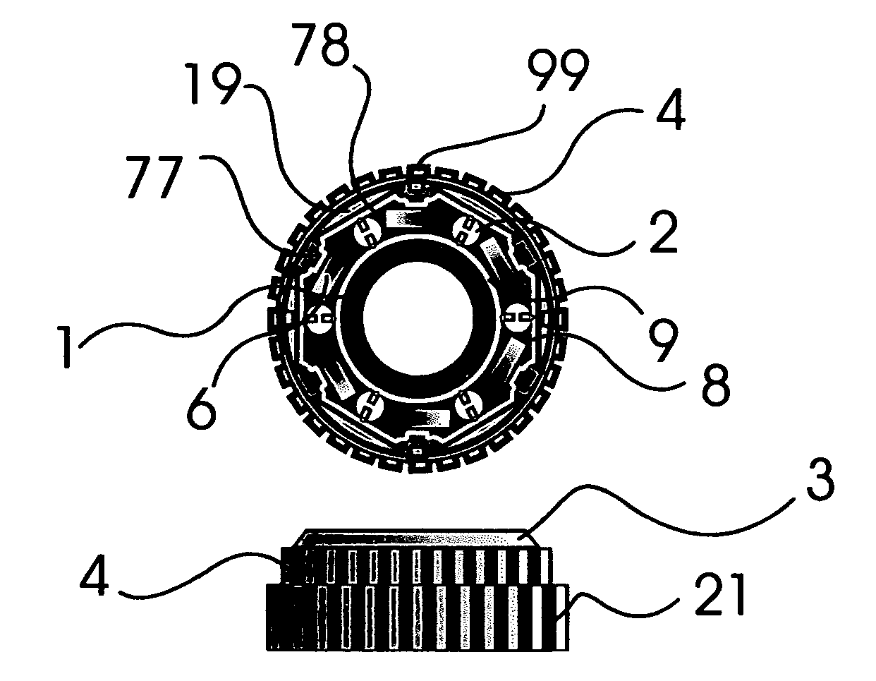
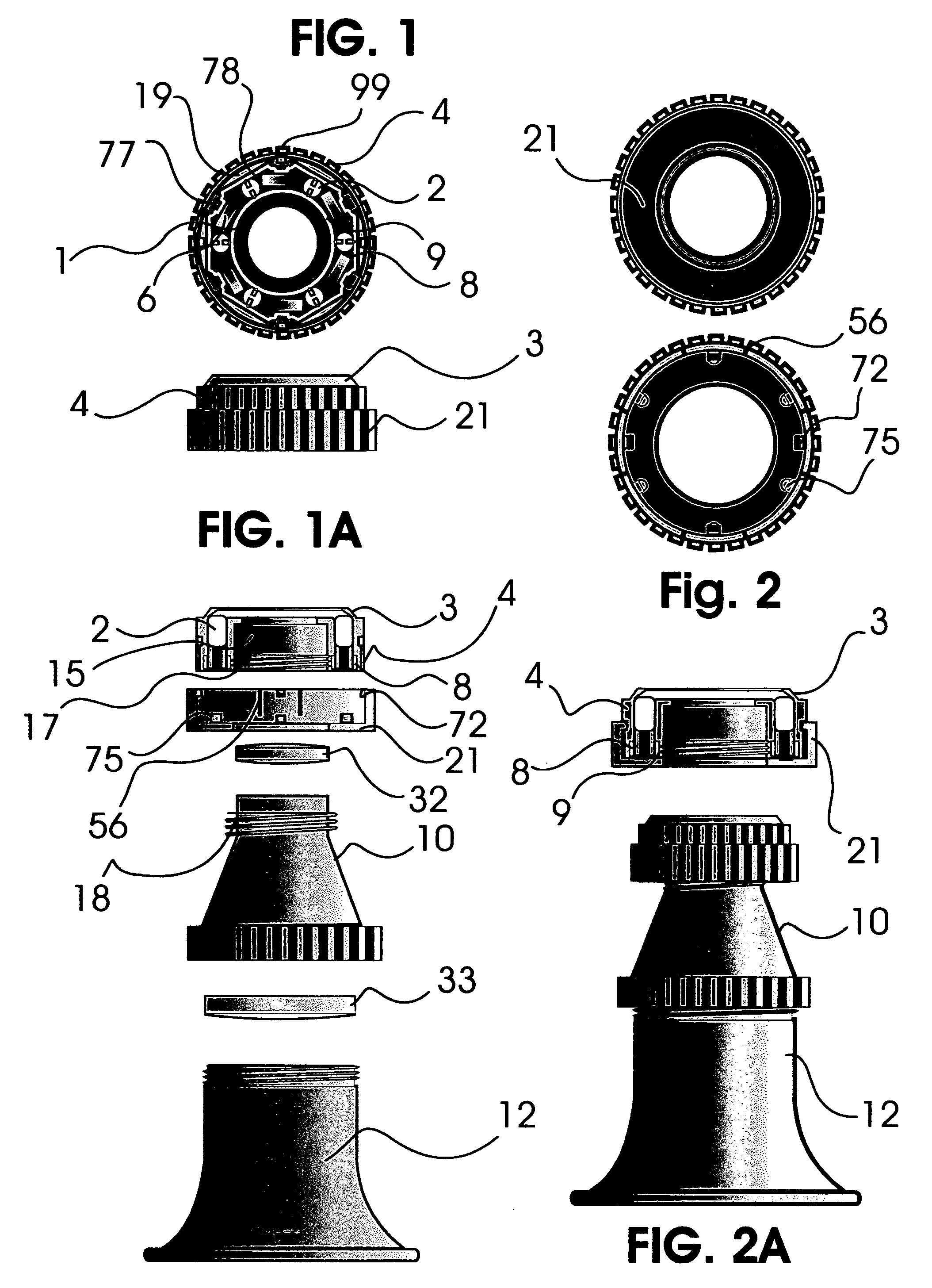
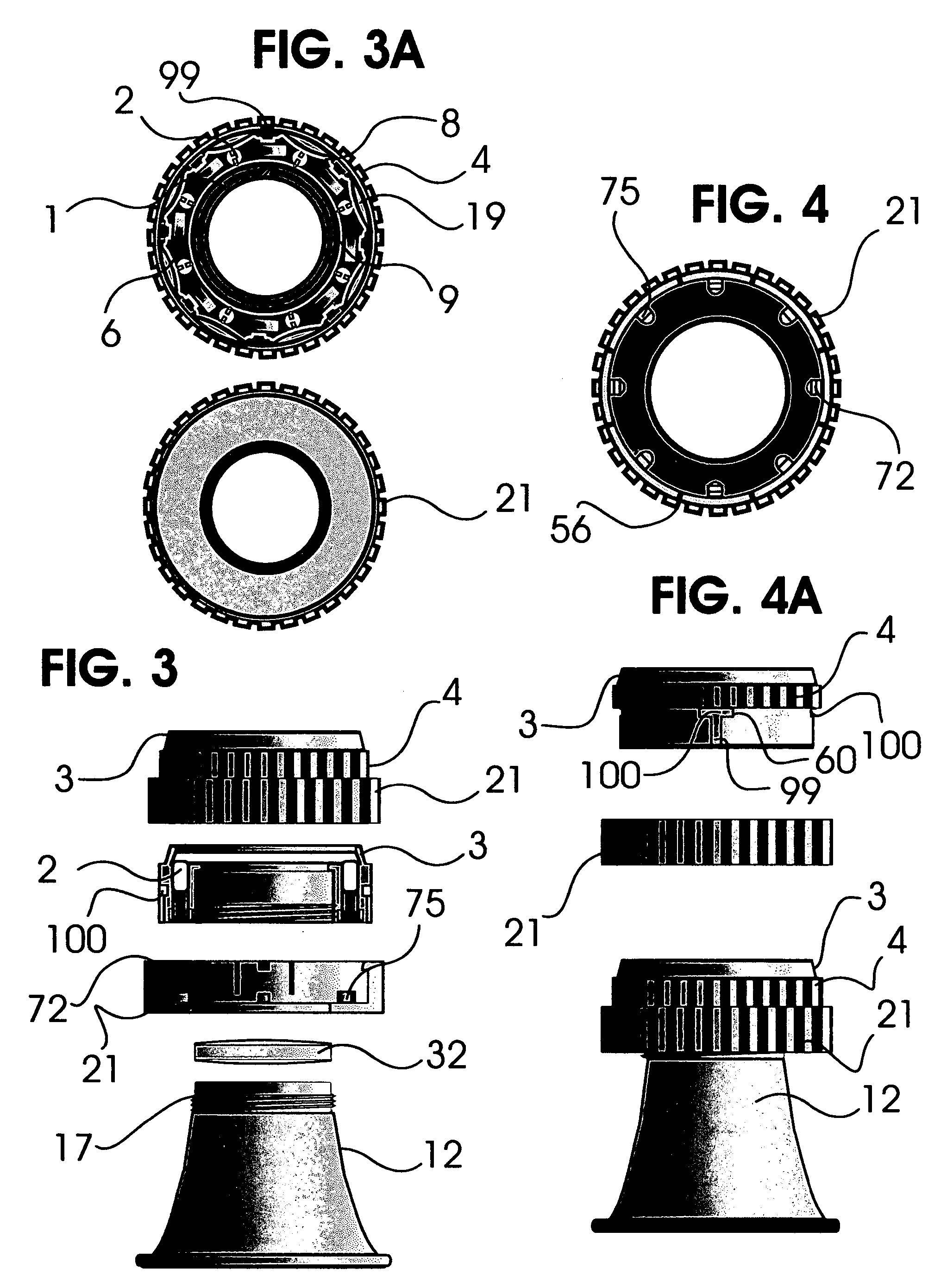
[0035] The foregoing is a description in detail of the preferred embodiment of the present invention. Referring to FIG. 1 there is shown in the drawings housing 4 of which is comprised of two parts: upper housing 4 and the back and lower housing 21, both of which would be fabricated of a light weight suitable plastic, resin or appropriate material for housing a light source and compatible with circuitry. The upper housing 4 is provided with chamber(s) 50, which are adapted to receive led(s) (light emitting diode(s) 2 as best seen in FIG. 6, when multiple led(s) (light emitting diode(s) are employed, chamber(s) 50 are spaced apart. Also seen in FIG. 1 within upper housing 4 and better seen in FIG. 6, is recess 78, which is fashion to receive positive contact member 9 and negative contact member 8 when fully assembled. Positive contact member 9 and negative contact member 8 would be made of a suitable material for conducting electrical current and also allow for a modicum amount of fl...


PUM


Abstract

A lighted lens housing is provided, having led(s) placed in progression around a lens opening. The light generated from led(s) is directed to a desired focal point by means of deflector ring found adjacent the outer edge of led(s). A central lens channel is provided for the insertion and placement of a desired lens. A threaded opening at one end of lens channel for attachment to a typical jewelers loupe. Electrical power is provided by button cell battery.

Description

CROSS-REFERENCE TO RELATED APPLICATIONS [0001] The present application is based on, and claims priority from, provisional application Ser. No. 60 / 797588, Filed May 4, 2006, entitled “LIGHTED LENS HOUSING FOR JEWELLERS LOUPE”, which is incorporated herein in it's entirety by reference.STATEMENT REGARDING FEDERALLY SPONSORED RESEARCH OR DEVELOPMENT [0002] N / A REFERENCE TO APPENDIX [0003] N / A BACKGROUND OF THE INVENTION [0004] 1. Field of the Invention [0005] The present invention relates generally to a lens housing and more specifically to a lens housing which incorporates illumination with intent to provide a 360-degree use of light in conjunction with an inserted magnification lens from a Jewelers loupe and attachment to the same. [0006] 2. Description of the Related Art [0007] Illumination in conjunction with magnification has always been an issue since the inception of the magnification lens. The limitations imposed by daylight hours and available light, have encouraged those conc...

Claims


Application Information

Patent Timeline
Patent Type & Authority Applications(United States)
IPC IPC(8): F21V15/00
CPCG02B25/02
Inventor DUHE, JERRY
Owner DUHE JERRY
Why Eureka
Try Eureka