Cannulated bone screw system and method

a bone screw and cannula technology, applied in the field of bone screw system and method, can solve the problems of very time-consuming, each step the entire process is very time-consuming, so as to reduce the force, minimize or prevent the device from protruding

Active Publication Date: 2007-11-08
ORTHOIP
View PDF99 Cites 80 Cited by
  • Summary
  • Abstract
  • Description
  • Claims
  • Application Information

AI Technical Summary

Benefits of technology

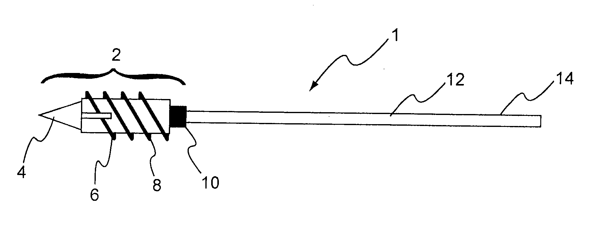
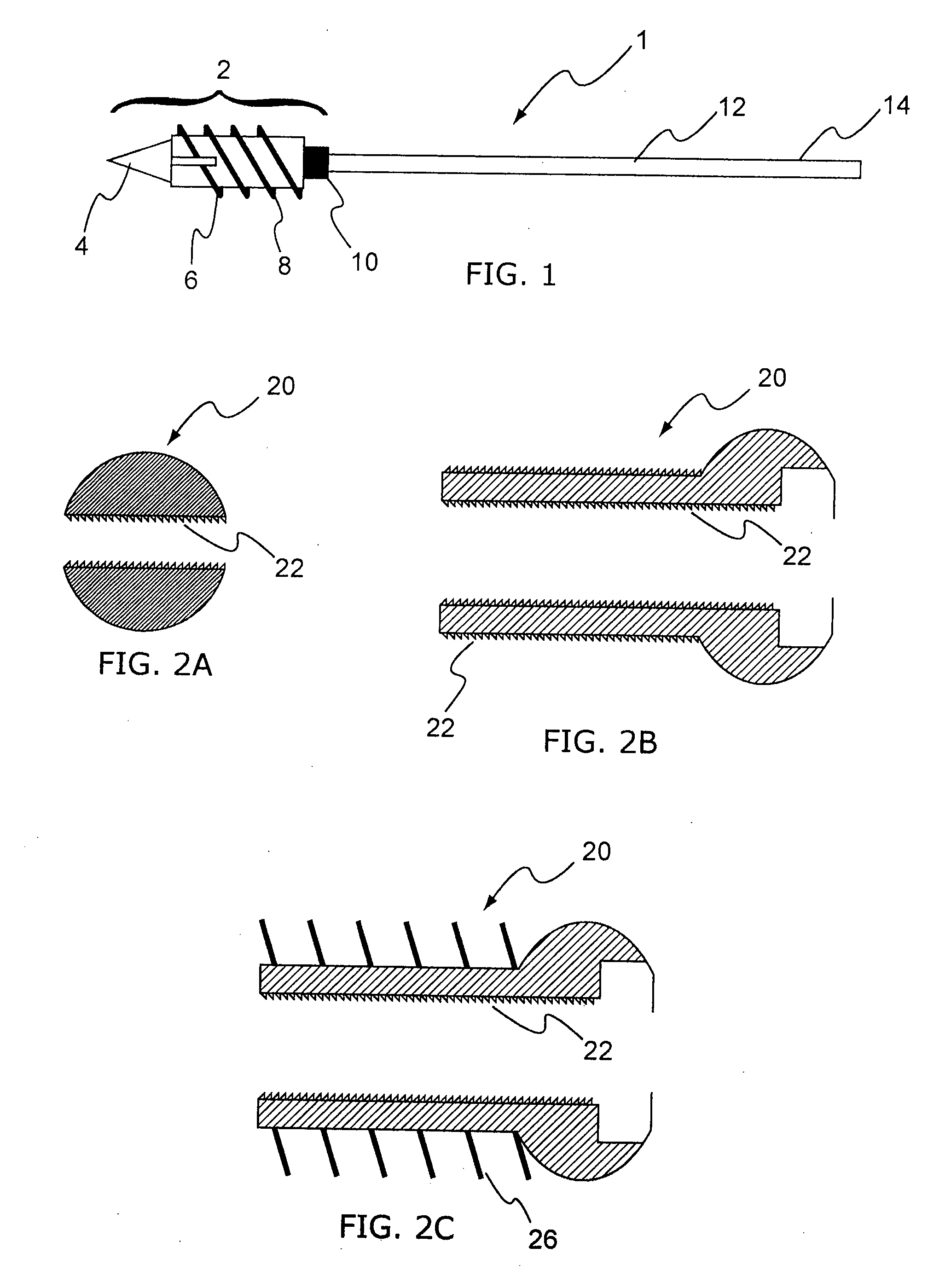
[0012] In another embodiment, the invention includes a shaft with distal portion having a threaded surface thereon, a sleeve having an opening which receives the shaft such that the shaft is able to move within the sleeve with minimal or no movement of the sleeve. In one embodiment, a compressive device (e.g., spring) exists between the sleeve and the proximal portion of the shaft such that the compressive device exerts a force directly or indirectly against the shaft and the sleeve. In one embodiment, the compressive device is located inside the sleeve. The compressive device exerts a force which serves to move the distal head and the proximal sleeve toward each other, thereby maintaining the compressive load at the union of the fracture. As additional compression is exerted on the fracture from weight bearing, the force may be reduced, but the head of the sleeve is still substantially maintained against the lateral cortex. The sleeve may be maintained against the lateral cortex until sufficient collapse of the fracture occurs such that the compressive device no longer exerts a force against the sleeve or shaft, then the device may simply act as a traditional bone screw. As such, the improved bone screw of the present invention minimizes or prevents the device from protruding beyond the bone, and maintains the compression across the fracture during fracture collapse. The bone screw of the present invention may be used in place of any existing bone screw, or any existing component of a product that performs a similar function as a bone screw.

Problems solved by technology

However, the insertion of existing screws through or around fractures has disadvantages.
For example, the entire process is very time-consuming because inserting a regular screw usually involves multiple steps such as drilling the pilot hole, measuring the relevant distances to determine the appropriate screw selection, tapping the hole to establish threads and screwing the screw into the hole.
Again, each step and the entire process is very time-consuming.
In addition to the length and complexity of the process, the prior art system also typically includes inadequate components.
For example, in poor bone, prior art screws often loose their grip and strip out of the bone.
Currently available bone screws also typically provide only one side of cortex fixation and are generally not suited for percutaneous surgery.
Moreover, when placing the screws in the bone, the physician may not accurately set the screw into the distal hole or may miss the distal hole completely, thereby resulting in the screw stripping the threads or breaking the bone.
Because the physician typically is unable to accurately determine the type or size of screw needed until the physician enters the bone and measures the appropriate screw placement, operating facilities need to store and make available large inventories of screws.
Furthermore, if cannulated screws are desired, another entire screw set of over one hundred additional screws is often needed.
As such, inventory management of screws is a very large problem for many operating facilities.
Such micro-motion has an affect on the bone screw in that the micro-motion often causes the bone screw to slide within the bone, thereby disrupting the bone union.
The bone union is disrupted because the union loses its fixed compression and fracture interface is decompressed.
In some cases, the head of the bone screw may protrude about 1 cm which may result in pain and / or the need for additional surgery.

Method used


Image

  • Cannulated bone screw system and method
  • Cannulated bone screw system and method
  • Cannulated bone screw system and method

Examples


Embodiment Construction

[0040] The present invention is described herein and includes various exemplary embodiments in sufficient detail to enable those skilled in the art to practice the invention, and it should be understood that other embodiments may be realized without departing from the spirit and scope of the invention. Thus, the following detailed description is presented for purposes of illustration only, and not of limitation, and the scope of the invention is defined solely by the appended claims. The particular implementations shown and described herein are illustrative of the invention and its best mode and are not intended to otherwise limit the scope of the present invention in any way.

[0041] In general, the present invention facilitates the change in distance between objects or surfaces, compresses objects together and / or provides a configurable or random amount of pressure between surfaces. The system may facilitate changing, maintaining, reducing and / or expanding the distance between obje...


PUM


Abstract

An improved bone screw is disclosed which includes a shaft with distal portion having a threaded surface thereon, a sleeve having an opening which receives the shaft such that the shaft is able to move within the sleeve without moving the sleeve. A compressive device may be incorporated between the sleeve and the proximal portion of the shaft such that the compressive device forces the shaft and sleeve towards each other, thereby maintaining the compressive load at the union of the fracture. As additional compression is exerted on the load from weight bearing, the force may be reduced, but the head of the sleeve is still substantially maintained against the lateral cortex.

Description

CROSS-REFERENCE TO RELATED APPLICATIONS [0001] This application is a continuation-in-part of U.S. Ser. No. 11 / 678,473, which itself is a continuation-in-part of, and claims priority to, U.S. Ser. No. 10 / 779,892 filed on Feb. 17, 2004 and entitled System And Method For The Fixation Of Bone Fractures which itself claims priority to U.S. Ser. No. 10 / 272,773 filed on Oct. 17, 2002 with the same title (now U.S. Pat. No. 6,736,819). The '819 patent itself claims priority to U.S. Provisional Application Ser. No. 60 / 330,187, entitled Lagwire System And Method filed Oct. 18, 2001, all of which are incorporated herein by reference.FIELD OF INVENTION [0002] The invention generally relates to a system and method for the fixation of fractures in one or more objects, and more particularly, to a bone screw for the fixation of bone fractures which collapses along with the fracture collapse to minimize protrusion of the device beyond the bone surface, and to maintain compression across the fracture ...

Claims


Application Information

Patent Timeline
Patent Type & Authority Applications(United States)
IPC IPC(8): A61B17/58
CPCA61B17/62A61B17/8869A61B17/683A61B17/685A61B17/7001A61B17/72A61B17/7225A61B17/725A61B17/742A61B17/744A61B17/746A61B17/80A61B17/842A61B17/864A61B17/8685A61B17/88A61B17/8863A61B17/68
Inventor TIPIRNENI, KISHORE
Owner ORTHOIP
Why Eureka
Try Eureka