
Airborne platform protection apparatus and associated system and method

a platform protection and airborne technology, applied in the direction of ammunition, weapons, ammunition projectiles, etc., can solve the problems of commercial aircraft being vulnerable to attack, rockets and missiles, undesirable risks to the platform being protected, etc., and achieve the effect of reducing the velocity

Inactive Publication Date: 2007-11-15
CHANG IND INC
View PDF25 Cites 79 Cited by
  • Summary
  • Abstract
  • Description
  • Claims
  • Application Information

AI Technical Summary

Benefits of technology

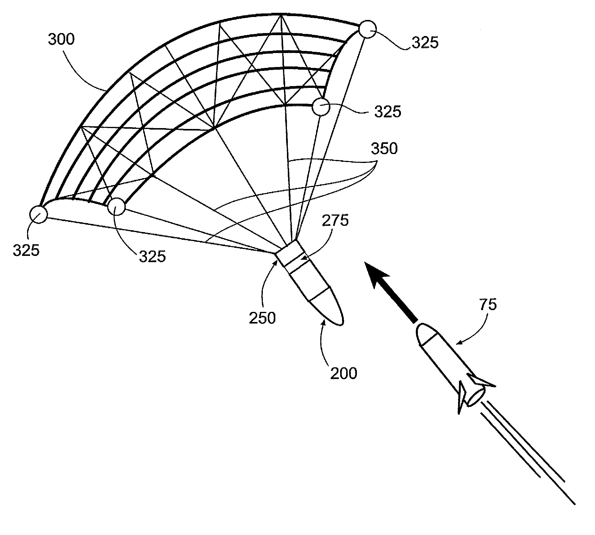
[0012] Yet another advantageous aspect of the present invention comprises a method of protecting a moving platform against an incoming threat having a mass. Such a method comprises deploying a protection apparatus from the moving platform in a first direction toward a threat in response to detection thereof, with the threat moving in a second direction toward the moving platform at a threat velocity. The protection apparatus has a mass and comprises a projectile housing having a first and a second deployable device operably engaged therewith. The first deployable device is deployed from the projectile housing to capture the threat such that the protection apparatus mass is combined with the threat mass via the first deployable device. The second deployable device is then deployed from the projectile housing, upon the first deployable device capturing the threat, such that the second deployable device decreases the velocity of the combined protection apparatus and threat masses in the second direction.
[0013] Embodiments of the present invention thus provide a protection apparatus having certain advantageous features. For example, some embodiments implement a cuing sensor that is capable of, for instance, detecting the threat(s); discriminating the threat(s) from non-threats; determining the threat flight path, including distance, speed, and angular position, to determine if the platform to be protected will actually be threatened; timely directing the launch of an appropriate protection apparatus to capture the threat and prevent the threat from reaching the platform or otherwise disabling or deflecting the threat. Accordingly, a protection apparatus can be timely launched with an appropriate launch time and exit speed so to engage the threat at a pre-determined safe distance (otherwise referred to herein as the intercept distance) from the platform. Embodiments of the present invention therefore meet the above-identified needs and provide significant advantages as further detailed herein.

Problems solved by technology

Many aircraft such as, for example, commercial aircraft are vulnerable to attack, such as with rockets and missiles, during take-off and landing, generally at a low altitude and low airspeed.
However, such active protection systems utilize an interceptor carrying an explosively-loaded warhead, which may result in undesirable risk to the platform being protected in instances where the platform is, for example, a commercial aircraft.
That is, the explosive warhead carried by the interceptor and used to defeat the threat may result in an undesirable risk to a commercial aircraft upon the explosion resulting from the threat being defeated.
For example, a CE threat can be defeated by a fragmenting or blasting type of CM that can hit one or more critical locations of the warhead of the threat such that the warhead is asymmetrically detonated and thus becomes unable to form a penetrator or a penetrating jet typically characterizing such a threat, since simply destroying the body of the CE threat could still allow the penetrator formation and result in the piercing of the armor of and subsequent damage to the platform.
However, the resulting explosions of the CM, and possibly the warhead of the threat, would represent a high risk to a slow-moving airborne platform.

Method used


Image

  • Airborne platform protection apparatus and associated system and method
  • Airborne platform protection apparatus and associated system and method
  • Airborne platform protection apparatus and associated system and method

Examples


Embodiment Construction

[0019] The present invention now will be described more fully hereinafter with reference to the accompanying drawings, in which some, but not all embodiments of the invention are shown. Indeed, this invention may be embodied in many different forms and should not be construed as limited to the embodiments set forth herein; rather, these embodiments are provided so that this disclosure will satisfy applicable legal requirements. Like numbers refer to like elements throughout.

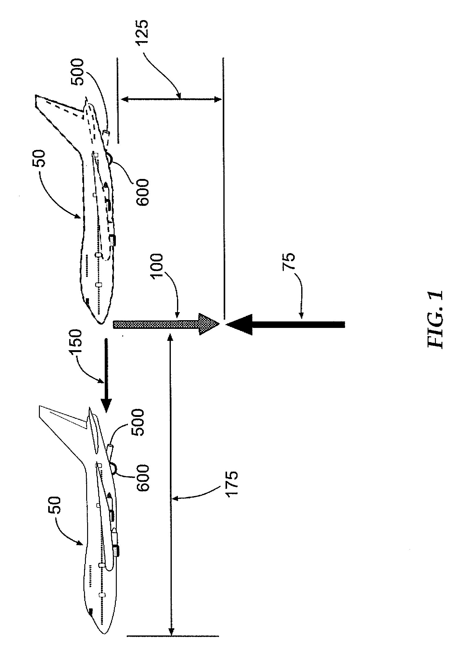
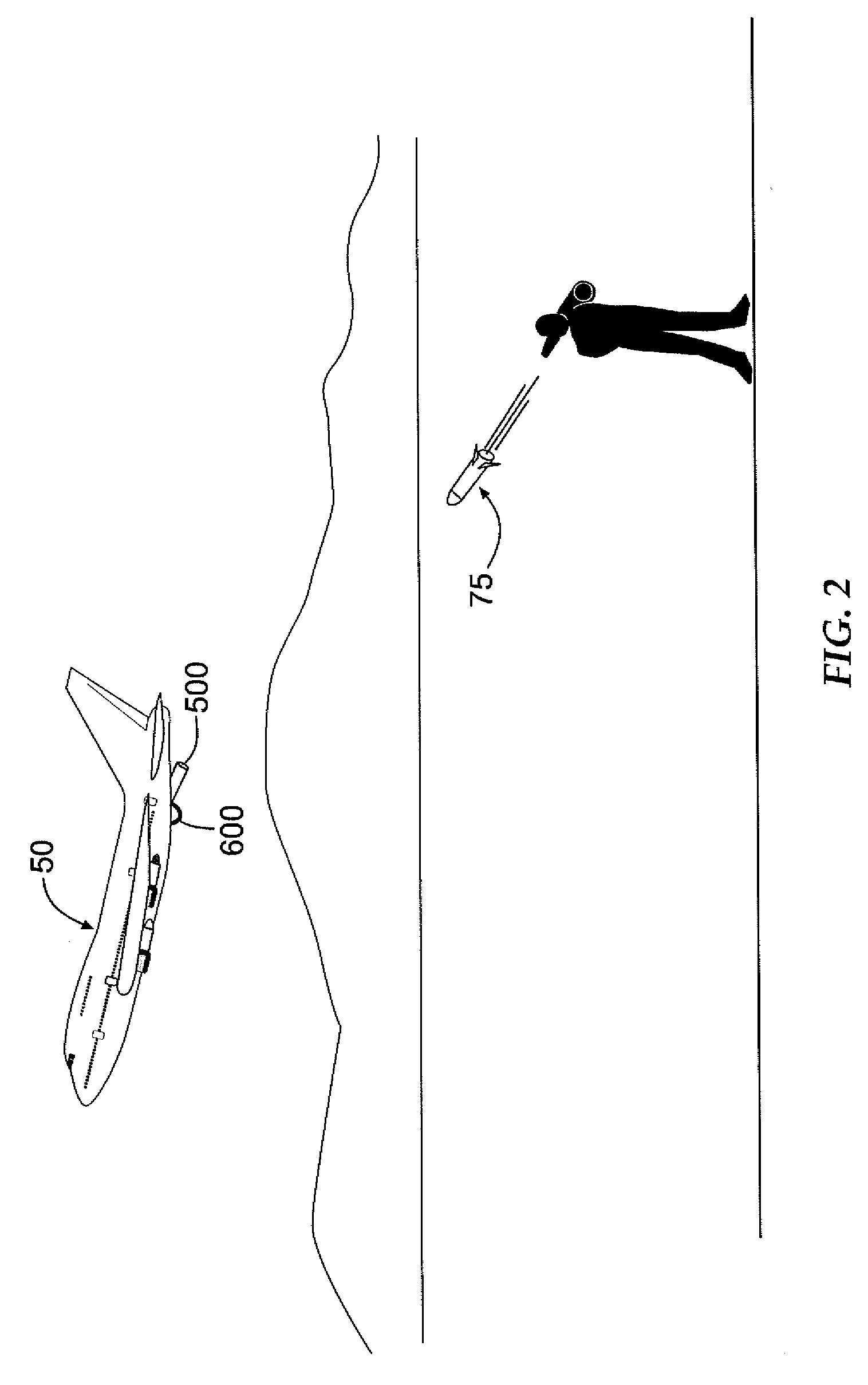
[0020]FIGS. 1 and 2 schematically illustrate functionality of a protection apparatus according to one embodiment of the present invention, such a protection apparatus being indicated by the numeral 100 for protecting a moving airborne platform 50 against an incoming threat 75. In such a scenario, the threat 75 (such as, for example, an unguided rocket, or an optical, radar or infrared guided / heat-seeking missile) has a weight Wthreat (and corresponding mass) and an approaching velocity Vthreat toward the airborn...


PUM


Abstract

A protection apparatus adapted to protect a moving platform against an incoming threat is provided. The protection apparatus is deployed from the moving platform in a first direction toward the threat, with the threat moving in a second direction toward the moving platform at a threat velocity. The protection apparatus comprises a projectile housing. A first deployable device is operably engaged with the projectile housing, and is adapted to capture the threat upon deployment such that the protection apparatus mass is combined with the threat mass via the first deployable device. A second deployable device is operably engaged with the projectile housing, and is configured to be deployed upon the first deployable device capturing the threat. The second deployable device is further configured to decrease the velocity of the combined protection apparatus and threat masses in the second direction. Associated systems and methods are also provided.

Description

BACKGROUND OF THE INVENTION [0001] 1. Field of the Invention [0002] The present invention relates to a defensive device and, more particularly, to a protection apparatus and associated system and method for protecting an airborne platform from an incoming threat. [0003] 2. Description of Related Art [0004] Many aircraft such as, for example, commercial aircraft are vulnerable to attack, such as with rockets and missiles, during take-off and landing, generally at a low altitude and low airspeed. Some active protection systems have been developed that can be implemented to destroy the warhead section of such threats using a threat-defeating interceptor having its own warhead that can be launched from platforms such as airborne helicopters and armored ground vehicles protection. However, such active protection systems utilize an interceptor carrying an explosively-loaded warhead, which may result in undesirable risk to the platform being protected in instances where the platform is, fo...

Claims


Application Information

Patent Timeline
IPC IPC(8): F41F5/00
CPCF41H11/02F42B12/68F41H13/0006
Inventor CHANG, YU-WENLEE, TRONG-HUANG
Owner CHANG IND INC
Learn More