Heat exchanger having different flowing paths

a technology of heat exchanger and flowing path, which is applied in the field of heat exchanger, can solve the problems of not being able to facilitate the heat exchange effect, and achieve the effect of facilitating the heat exchange

Inactive Publication Date: 2007-11-15
KAORI HEAT TREATMENT COMPANY
View PDF7 Cites 17 Cited by
  • Summary
  • Abstract
  • Description
  • Claims
  • Application Information

AI Technical Summary

Benefits of technology

[0009] The primary objective of the present invention is to provide a heat exchanger including two or more different or uneven fluid flowing paths or passages having different cross section areas or different volumes for guiding and allowing the heat medium and / or other heat exchanging fluids to flow through the fluid flowing paths or passages with different flowing speeds and / or different contact areas, and for facilitating the heat exchanging effect.

Problems solved by technology

However, the heat dissipating or absorbing or exchanging rate of the different heat exchanging fluids, such as water, heat or cold media, or the like may be different from each other, such that the heat exchanging rate between the different heat exchanging fluids may be different, and such that the heat exchanging effect may not be facilitated.

Method used


Image

  • Heat exchanger having different flowing paths
  • Heat exchanger having different flowing paths
  • Heat exchanger having different flowing paths

Examples


Embodiment Construction

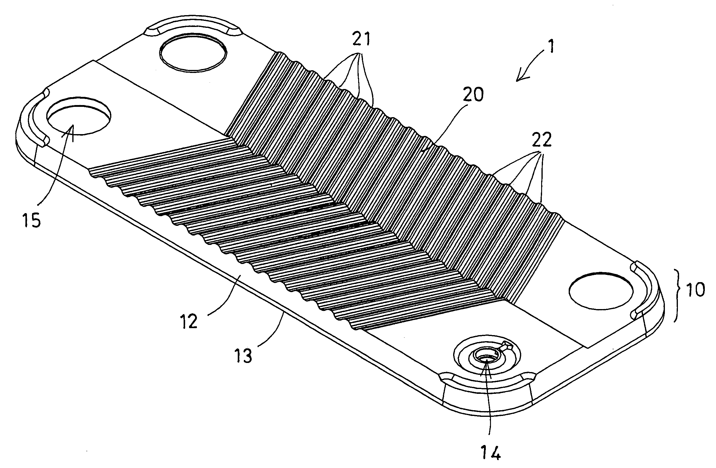
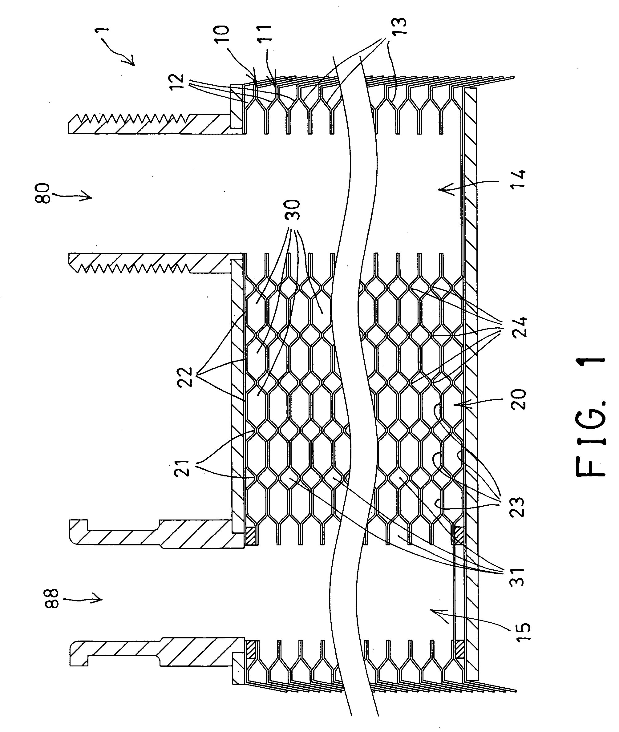
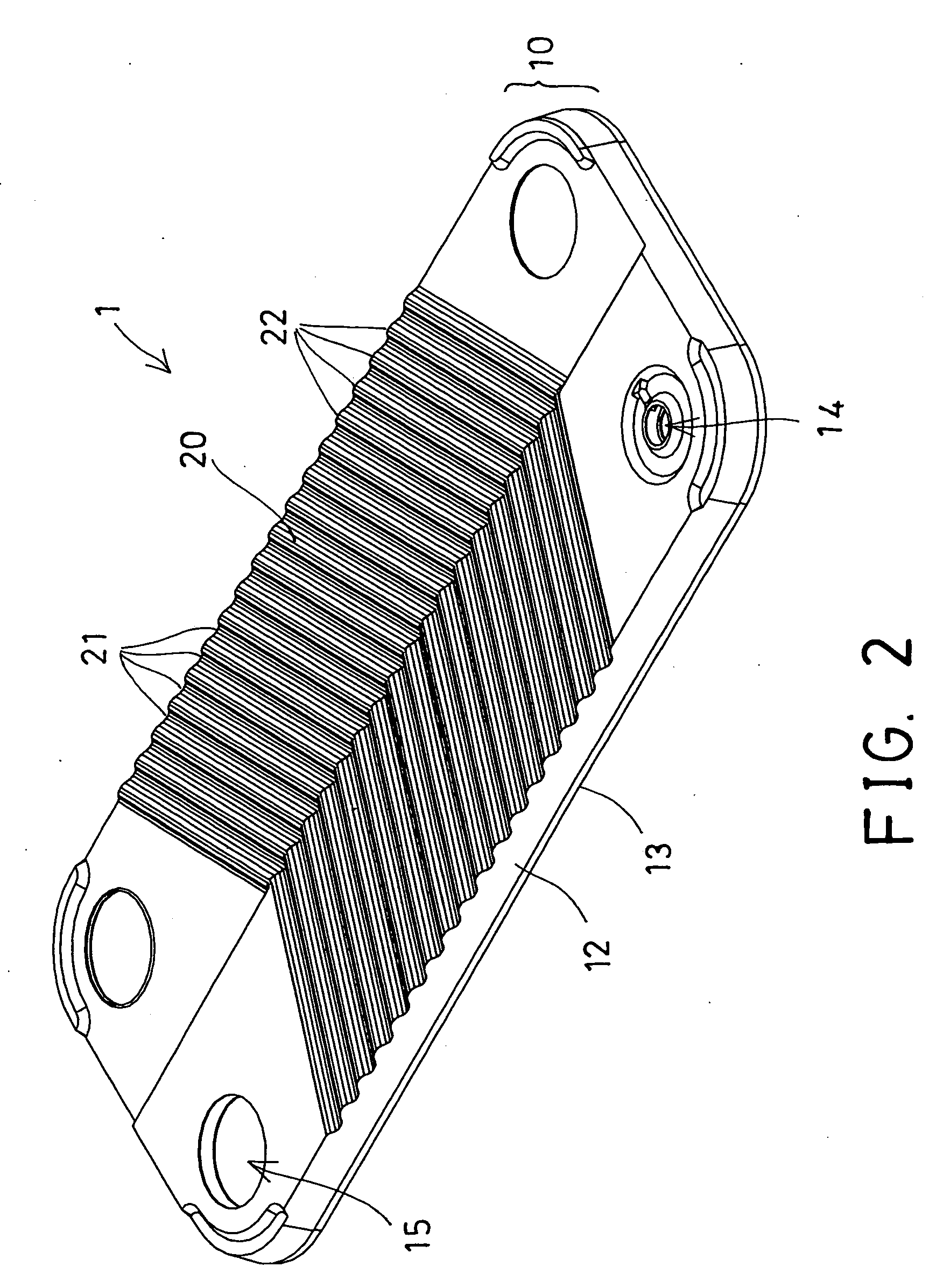
[0018] Referring to the drawings, and initially to FIGS. 1-2, a heat exchanger 1 in accordance with the present invention comprises one or more heat exchanging assemblies or plate sets 10, 11 alternatively superposed with each other and each including two heat exchanging boards or plates 12, 13 disposed and superposed with each other for allowing the upper or first plate 12 to be disposed above the lower or second plate 13 which is disposed above the upper or first plate 12 of the other or lower plate set 11. The plates 12-13 each include a wavy structure 20 arranged to allow the heat medium or water or fluid to flow through the wavy boards or plates 12-13 with an increased contacting area, and to allow the heat medium or water or fluid to be heat exchanged with the other heat medium, such as ambient air, other heat media or water or fluid or the like.

[0019] The formation or the provision of the wavy structure 20 of the boards or plates 12-13 is provided for increasing the contacti...


PUM


Abstract

A heat exchanger includes a number of plate sets disposed one above the other or superposed with each other, and each plate sets includes an upper plate and a lower plate for forming one or more conduits between the upper and the lower plates, and for forming one or more ducts between the lower and the upper plates of different plates, the plates include an opening communicating and coupled to the conduits for receiving one heat medium, and an orifice communicating and coupled to the ducts for receiving a different heat medium and for separating the heat media from each other, and for allowing the heat media to have different flowing quantity from each other.

Description

BACKGROUND OF THE INVENTION [0001] 1. Field of the Invention [0002] The present invention relates to a heat exchanger, and more particularly to a heat exchanger having two or more different or uneven fluid flowing paths or passages having different cross section areas or different volumes for guiding and allowing the heat medium and / or other heat exchanging fluids to flow through the fluid flowing paths or passages with different flowing speeds and / or different contact areas, and for facilitating the heat exchanging effect. [0003] 2. Description of the Prior Art [0004] Typical heat exchangers comprise a receptacle including a chamber formed therein for receiving a heat medium, such as water or fluid, and an inlet and an outlet provided therein for allowing the heat medium or water or fluid to flow into and out of the chamber of the receptacle. The receptacle further includes a number of plates or boards or housings disposed therein, and superposed with each other, and each having a ...

Claims


Application Information

Patent Timeline
Patent Type & Authority Applications(United States)
IPC IPC(8): F28F3/00
CPCF28F3/046F28D9/005
Inventor YANG, CHIEN-YUHLIN, YUE-HUNGCHENG, MING CHEHOU, BO-WEN
Owner KAORI HEAT TREATMENT COMPANY
Why Eureka
Try Eureka