Pallet and plasma processing equipment

A tray and processed technology, applied in semiconductor/solid-state device manufacturing, discharge tubes, electrical components, etc., can solve the temperature difference between the edge area of ​​the wafer and the center area, poor temperature uniformity of the processed workpiece, poor heat exchange effect, etc. problem, achieve the effect of reducing leakage, avoiding heat conduction efficiency and improving uniformity

Inactive Publication Date: 2014-10-29
BEIJING NAURA MICROELECTRONICS EQUIP CO LTD
View PDF4 Cites 7 Cited by
  • Summary
  • Abstract
  • Description
  • Claims
  • Application Information

AI Technical Summary

Problems solved by technology

And this can produce following problem: because the backside of wafer and the loading surface of tray closely fit, cause the gap between the backside of wafer and the loading surface of tray to be too small, this makes the heat exchanging gas in this gap mainly concentrate on Near the air inlet hole, it is difficult to diffuse to the edge of the wafer, resulting in poor heat exchange effect between the heat exchange gas and the edge area of ​​the wafer, which will cause a difference between the temperature of the edge area of ​​the wafer and the temperature of the center area, and the processed workpiece poor temperature uniformity
This will also lead to poor heat exchange between the heat exchange gas and the edge area of ​​the wafer, resulting in a difference between the temperature of the edge area of ​​the wafer and the temperature in the center area, and thus the temperature uniformity of the processed workpiece is poor

Method used


Image

  • Pallet and plasma processing equipment
  • Pallet and plasma processing equipment
  • Pallet and plasma processing equipment

Examples


Embodiment Construction

[0033] In order for those skilled in the art to better understand the technical solution of the present invention, the tray and the plasma processing equipment provided by the present invention will be described in detail below with reference to the accompanying drawings.

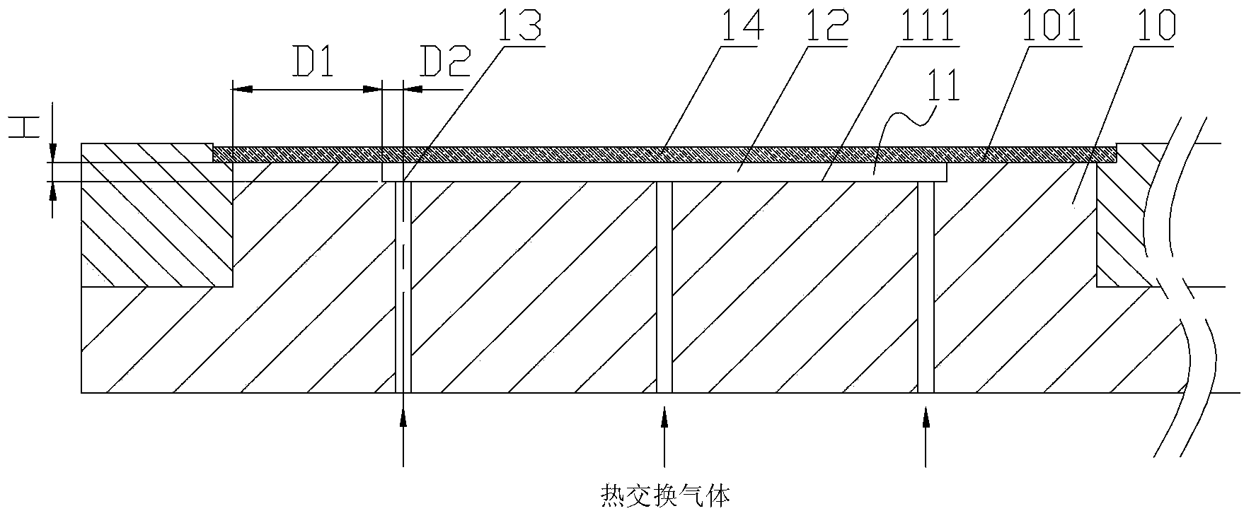
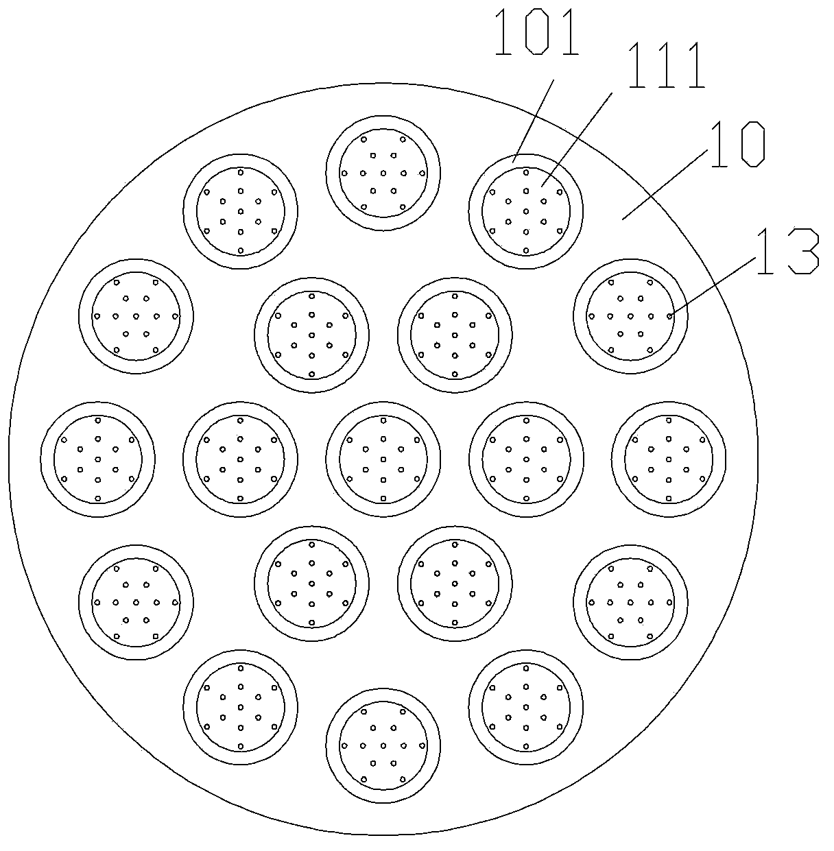
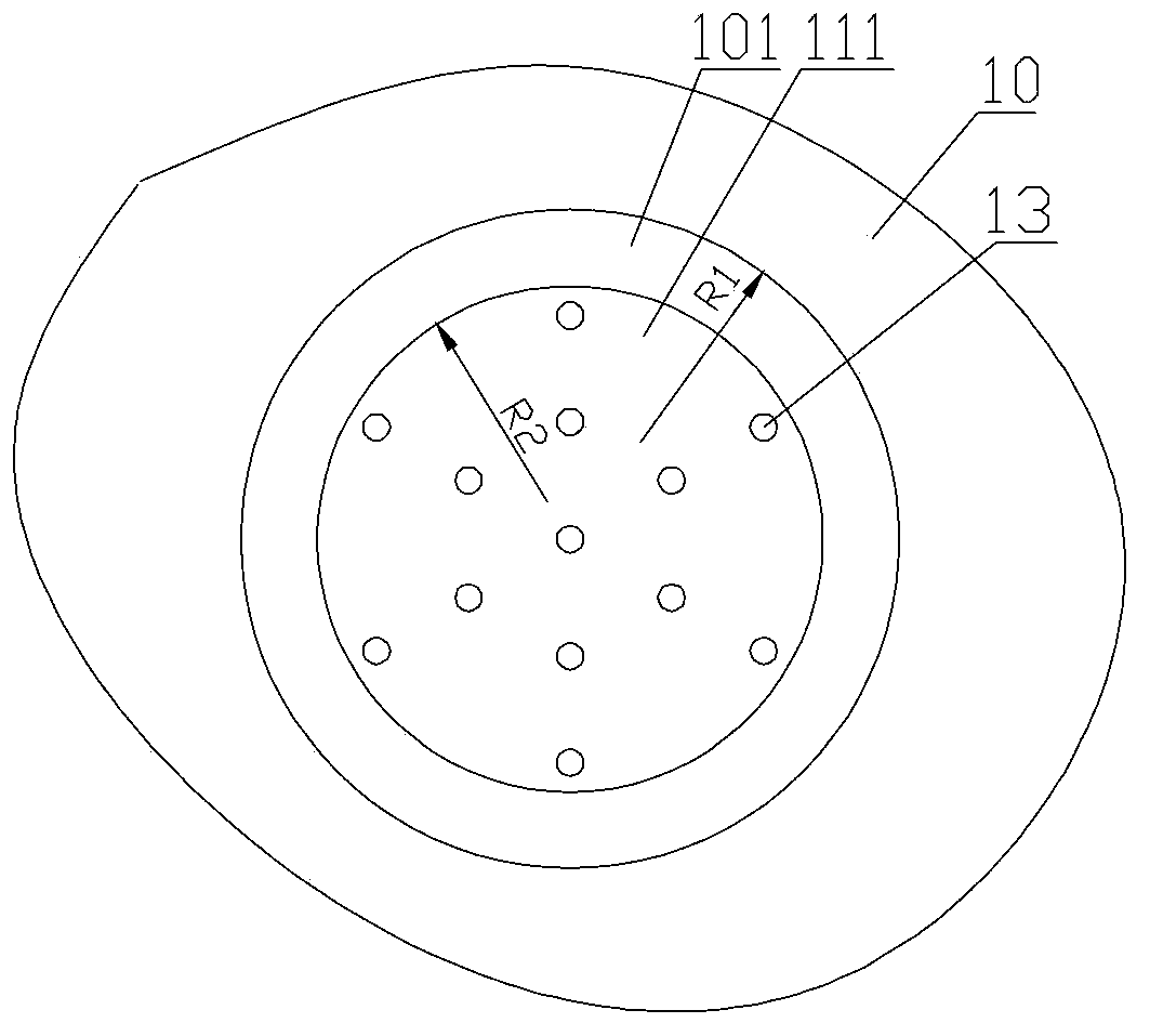
[0034] figure 1 Partial cross-sectional view of the pallet provided by the embodiment of the present invention. figure 2 A top view of the pallet provided by the embodiment of the present invention. image 3 for figure 2 A partial top view of the middle tray. Please also refer to figure 1 , figure 2 with image 3, the tray 10 is used to carry the workpiece 14 to be processed, and the temperature of the workpiece 14 to be processed is adjusted by means of a heat exchange gas such as helium, argon or nitrogen, and a recess 11 is formed on the upper surface of the tray 10, the recess The number and position of 11 correspond to the number and position of the workpiece 14 to be processed one by one, and...


PUM


Abstract

Disclosed are a pallet (10) and a plasma machining apparatus. The pallet (10) is used for bearing a machined work-piece (14), and adjusting the temperature of the machined work-piece (14) by means of a heat exchange gas, wherein at least one bearing region of the machined work-piece is formed on the upper surface of the pallet (10); the shape and size of each bearing region of the machined work-piece are corresponding to the machined work-piece (14) to be borne; at least one recess (11) which is recessed towards the lower surface of the pallet is formed in a non-edge region (111) of each bearing region of the machined work-piece; the maximum diameter of a notch of each recess (11) is smaller than the minimum diameter of the borne surface of the machined work-piece (14) to be borne; intake holes (13) are distributed on the bottom surface of the recess (11); and the intake holes (13) are connected to a gas source of the heat exchange gas. The pallet (10) can not only improve the efficiency and uniformity of heat exchange between the heat exchange gas and the machined work-piece (14), but can also reduce the leakage amount of the heat exchange gas.

Description

technical field [0001] The invention relates to the technical field of microelectronic processing, in particular to a tray and plasma processing equipment. Background technique [0002] Plasma processing equipment is a common equipment for processing semiconductor devices. During the process of etching, sputtering and chemical vapor deposition, etc., in order to improve the production efficiency of plasma processing equipment and reduce production costs, generally larger size The tray is used to carry multiple wafers and transport them to the reaction chamber at the same time, so as to realize the simultaneous processing of multiple wafers. [0003] During actual processing, the plasma formed in the reaction chamber tends to cause the temperature of the wafer to exceed the temperature required by the process, so it is necessary to control the temperature of the wafer. The traditional temperature control method is to blow heat exchange gas, such as helium, on the back side o...

Claims


Application Information

Patent Timeline
Patent Type & Authority Applications(China)
IPC IPC(8): H01J37/20H01J37/32
CPCH01L21/68771H01J37/32715H01L21/67109
Inventor 刘利坚
Owner BEIJING NAURA MICROELECTRONICS EQUIP CO LTD
Why Eureka
Try Eureka