
Convection oven with forced airflow circulation zones

a technology of convection oven and circulation zone, which is applied in the field of convection oven, can solve the problems of batter leaning, overbrowning the edges of bakery items such as cakes and muffins, and aggravating the problem of air temperature uniformity, so as to optimize convecting gas circulation, minimize heating time, and improve air temperature uniformity

Inactive Publication Date: 2006-01-12
WOLF APPLIANCE
View PDF26 Cites 41 Cited by
  • Summary
  • Abstract
  • Description
  • Claims
  • Application Information

AI Technical Summary

Benefits of technology

This solution ensures more even and efficient cooking by maintaining uniform air temperature distribution and reducing cooking time, while being cost-effective and adaptable to various cooking methods.

Problems solved by technology

A major problem in convection ovens used for cooking food has been obtaining uniform heating of the food products in the oven.
This problem is aggravated when food is placed on cooking racks at multiple elevations within the oven compartment.
However, unmanaged air flow can still be uneven, leading to undesirable drying of foods, causing batters to lean, and over-browning the edges of bakery items such as cakes and muffins.
Such a passive arrangement has no ability to manage airflow, however.
Because the heat source and the blower are physically separate, this system provides limited control over air temperature distribution.
Such an oven is limited, however, to food that fits into fixed-height compartments.
However, when food is placed in such an oven, the airflow can be significantly blocked, particularly in the non-horizontal plane, resulting in turbulence and reduction in airflow effectiveness.
Furthermore, the vertically circulating currents can experience divergent temperatures due to passive convection, leading to non-uniform temperature distribution.
Each of these approaches has complexity, space, and / or cost drawbacks.
Because opening the oven door dramatically disrupts the hot air temperature distribution in the oven cavity, a forced air system shortens the recovery time and thereby improves overall cooking time.
However, the improvement in recovery time in current convection ovens is limited by the airflow capacity that a single blower can provide to the oven cavity.

Method used


Image

  • Convection oven with forced airflow circulation zones
  • Convection oven with forced airflow circulation zones
  • Convection oven with forced airflow circulation zones

Examples


Embodiment Construction

[0034] An exemplary forced air convection oven in accordance with the present invention will be described in detail with reference to the attached figures. For convenience, the following description refers to air as the convecting gas; however, any suitable gas, examples of which include nitrogen, steam, combustion gases from a gas-fired heating element, or a combination of such gases, may be used as well. Similarly, the following description refers to use of food in the invention in a convection oven for cooking food. It should be understood, however, that the present invention may be used to process any material suitably processed in a convection oven, including materials processed using flow-through ovens such as solderable circuit boards or web materials.

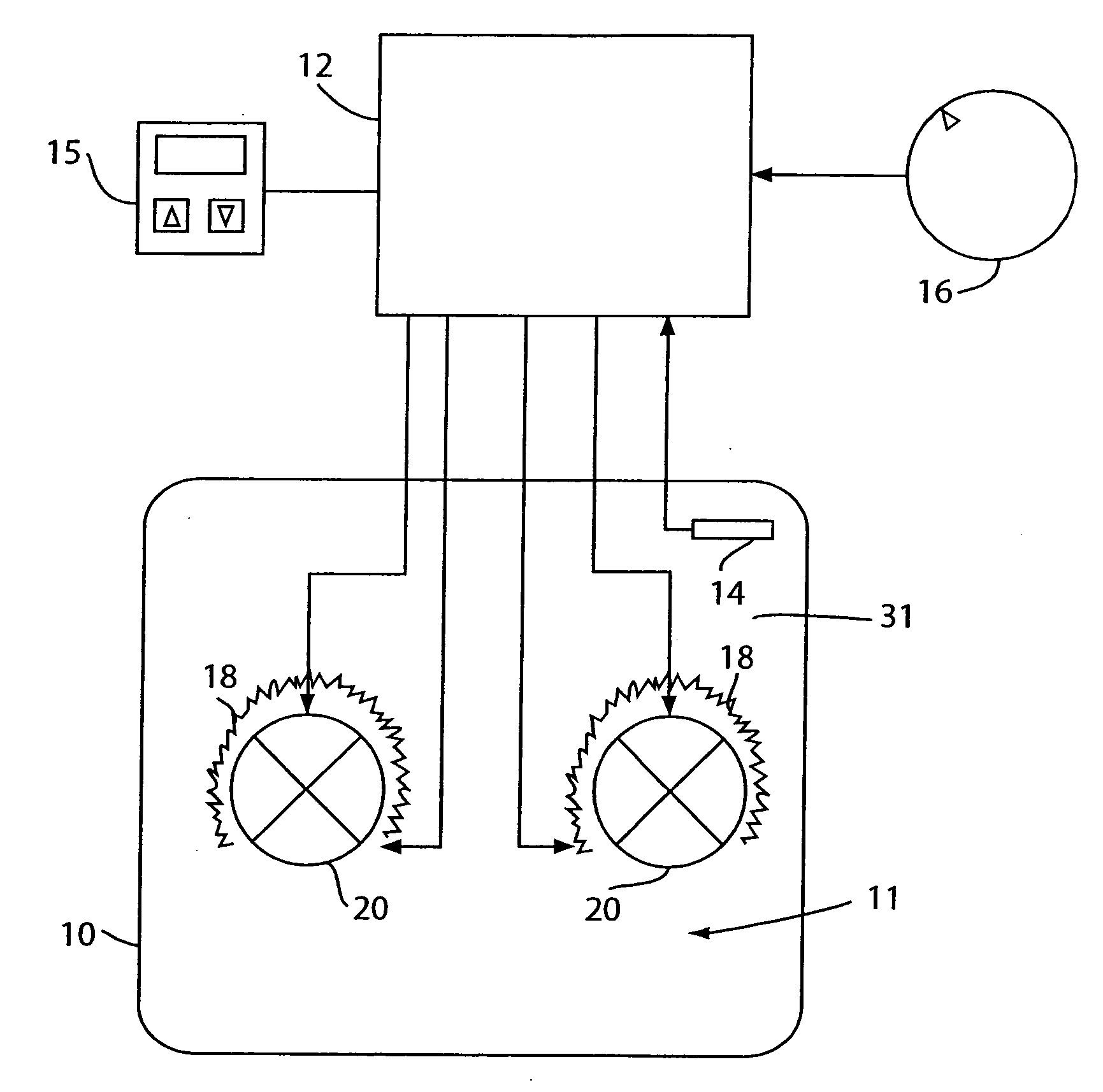
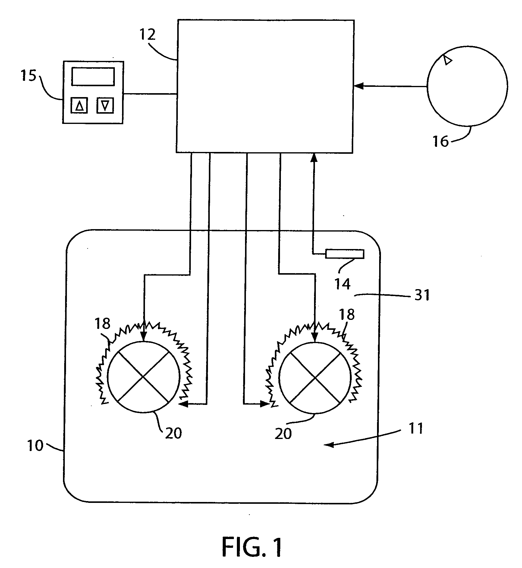
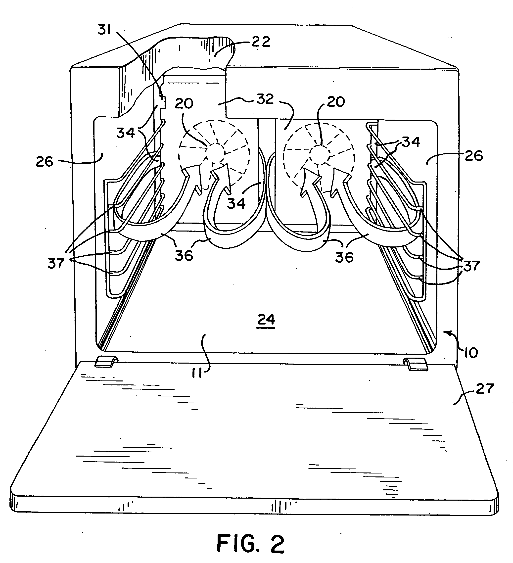
[0035] As shown in schematic view in FIG. 1, a forced air convection oven in accordance with the present invention may include an oven chamber 10 surrounding an internal cavity 11, a controller 12, a temperature sensor 14, a te...


PUM


Abstract

At least two blowers are controlled with baffles to create circulating zones of airflow which circulate in a substantially horizontal plane within a convection oven cavity. This airflow minimizes the potential for airflow paths to be broken up or blocked by the configuration of objects placed in the oven. The substantially horizontal airflow reduces the non-uniformity of air temperature distribution within the oven cavity. The blowers may be controlled to rotate either simultaneously or alternately, depending on the selected mode of operation. The blowers and associated heating elements are controlled to operate in various cooking modes by the controller in response to a mode selector input.

Description

REFERENCE TO RELATED APPLICATION [0001] This application is a continuation of application Ser. No. 10 / 233,156, filed Aug. 30, 2002, which is incorporated herein by reference.FIELD OF THE INVENTION [0002] This invention pertains generally to the field of convection ovens, and more particularly to convection ovens employing blowers to manage airflow in the oven cavity, and methods of controlling and using such ovens. BACKGROUND OF THE INVENTION [0003] A convection oven heats an object in an oven cavity by transferring heat energy from heating elements to the object by circulation of a gas within the oven cavity. Typically, a thermal sensor senses the temperature of the gas and a regulator controls the operation of the heating elements in response to the sensed temperature to maintain a desired operating temperature in the oven cavity. Although the circulated gas in a convection oven for cooking food is typically air, other gases may be employed such as nitrogen, steam, or combustion g...

Claims


Application Information

Patent Timeline
Patent Type & Authority Applications(United States)
IPC IPC(8): A21B1/00F24C15/32
CPCF24C15/325
Inventor CARBONE, PHILIPPESCATORE, PETERHOBSON, STEVEBREKKEN, MATTHEW
Owner WOLF APPLIANCE
Learn More