
Ceramic heater

a ceramic heater and ceramic technology, applied in the field of ceramic heaters, can solve the problems of cracks that are apt to be easily caused by the weight of the heater, the inclination of the silicon wafer placed on the metal plate, and the cracks of the heater

Inactive Publication Date: 2005-01-27
IBIDEN CO LTD
View PDF1 Cites 40 Cited by
  • Summary
  • Abstract
  • Description
  • Claims
  • Application Information

AI Technical Summary

Benefits of technology

The ceramic heater described in this patent is designed for use in semiconductor production and inspection equipment. It features a resistor heating body made of electrically conductive ceramic with a layer of sintering aid containing yttrium oxide or ytterbium oxide. This sintering aid layer prevents cracking and ensures efficient transfer of heat from the resistor heating body to the ceramic substrate. The heater is also designed to minimize temperature differences between the resistor heating body and the ceramic substrate, resulting in uniform temperature distribution. The use of a green sheet of electrically conductive ceramic with thickness scattering within ±10% of the average thickness helps achieve these results. Overall, the ceramic heater provides efficient heat transfer and uniform temperature distribution for semiconductor production equipment.

Problems solved by technology

In such a metallic heater, however, there is the following problem.
Because, the warp, strain or the like is caused in the thin metal plate due to thermal expansion resulted from the heating and hence the silicon wafer placed on the metal plate is broken or inclined.
However, as the thickness of the heater plate is made thick, there is a problem that the weight of the heater becomes heavy and bulky.
However, since tungsten is a metal and the difference in the thermal expansion coefficient between the ceramic and the metal is large, there is a problem that cracks are apt to be easily caused by rapid rising of the temperature.
In these heaters, however, pores are inevitably produced in an interface between the resistor heating body and the ceramic, so that there is caused a problem that these pores produce a delay in the heat transfer from the resistor heating body to a heating face of the ceramic substrate but also bring about the non-uniform temperature distribution.

Method used


Image

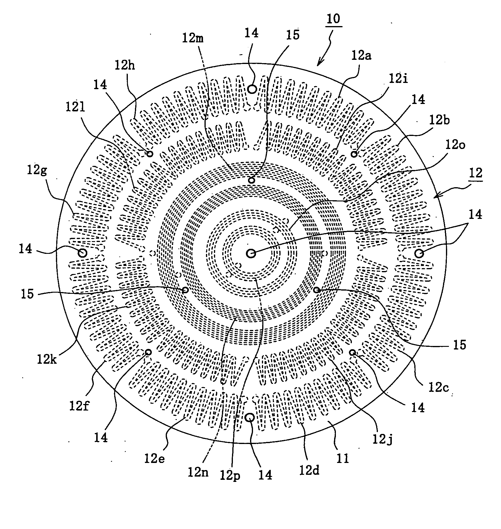
  • Ceramic heater
  • Ceramic heater
  • Ceramic heater

Examples


example 1

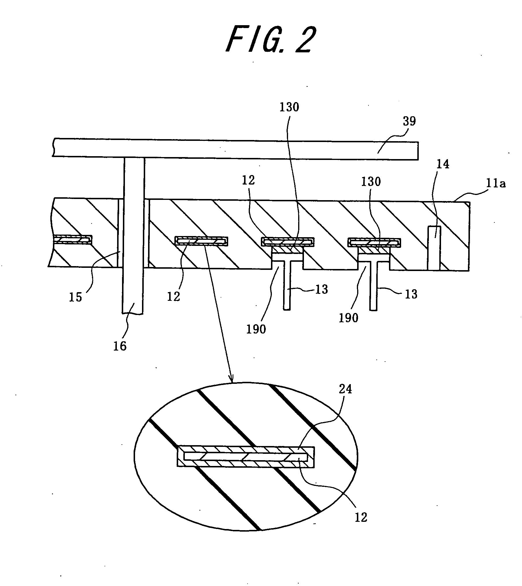
Production of Ceramic Heater (see FIGS. 1, 2 and 7)

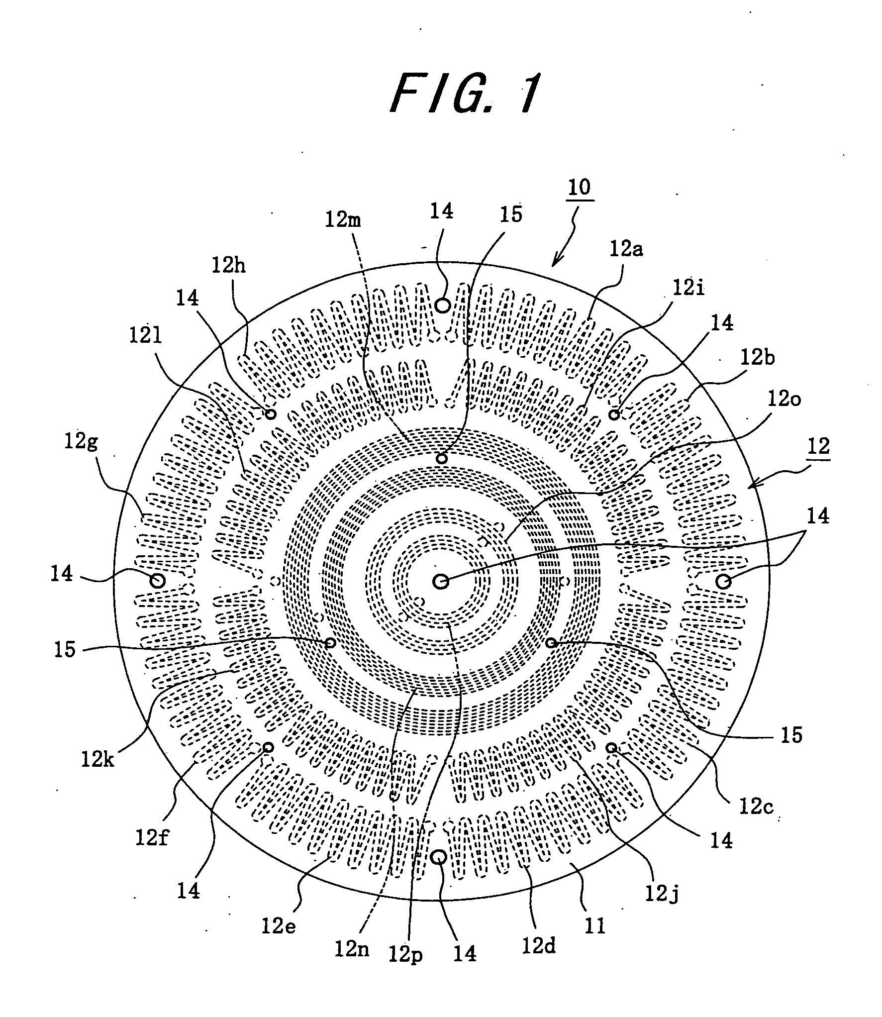
[0167] (1) A carbon sheet 42 is prepared by cutting a carbon block consisting of graphite and glassy carbon (made by IBIDEN Co., Ltd.: T-4 / ET-10) into a thickness of 200 μm. The carbon sheet 42 is subjected to a looter working to prepare a resistor heating body 12 having a pattern consisting of bending curve and concentric circles shown in FIG. 1.

[0168] Further, an aqueous solution of 1 mol / l yttrium nitrate is applied and dried on the surface of the resistor heating body 12.

[0169] (2) A plate-shaped body having a thickness of 1.5 mm is prepared by subjecting a paste of a mixture of 100 parts by weight of aluminum nitride powder (made by Tokuyama Co., Ltd. average particle size: 1.1 μm), 4 parts by weight of yttrium oxide (Y2O3: yttria, average particle size: 0.4 m), 11.5 parts by weight of acrylic resin binder, 0.5 part by weight of a dispersing agent and 53 parts by weight of an alcohol consisting of 1-butanol and ethanol to a ...

example 2

Production of Ceramic Heater (see FIGS. 1, 2 and 8)

[0180] (1) A carbon block consisting of graphite and glassy carbon (T-4 / ET-10, made by IBIDEN CO., Ltd.) is cut in a thickness of 0.6 mm to prepare a carbon sheet 52. This carbon sheet 52 is subjected to a looter working to prepare a resistor heating body 12 having a pattern consisting of bent curve and concentric circles as shown in FIG. 1.

[0181] (2) A plurality of green sheets 50 having a thickness of 0.47 mm are prepared by shaping a paste of a mixture of 100 parts by weight of aluminum nitride powder (made by Tokuyama Co., Ltd. average particle size: 1.1 μm), 4 parts by weight of yttrium oxide (Y2O3, average particle size: 0.4 μm), 11.5 parts by weight of an acrylic resin binder, 0.5 part by weight of a dispersing agent and 53 parts by weight of an alcohol consisting of 1-butanol and ethanol through a doctor blade process.

[0182] After the green sheet 50 is dried at 80° C. for 5 hours, a portion corresponding to a through-hole...

example 3

Production of Electrostatic Chuck (see FIG. 4)

[0189] (1) A carbon block consisting of graphite and glassy carbon (T-4 / ET-10, made by IBIDEN CO., Ltd.) is cut in a thickness of 0.6 mm to prepare a carbon sheet. This carbon sheet is subjected to a looter working to prepare a resistor heating body 320 having a pattern consisting of bent curve and concentric circles as shown in FIG. 1.

[0190] Further, an aqueous solution of 1 mol / l yttrium nitrate is applied onto the surface of the resistor heating body 320 and dried.

[0191] (2) Next, a sheet-shaped body having a thickness of 0.5 mm is prepared by shaping a paste of a mixture of 100 parts by weight of aluminum nitride powder (made by Tokuyama Co., Ltd. average particle size: 1.1 m), 4 parts by weight of yttrium oxide (Y2O3, yttria, average particle size: 0.4 μm), 11.5 parts by weight of an acrylic resin binder, 0.5 part by weight of a dispersing agent and 53 parts by weight of an alcohol consisting of 1-butanol and ethanol through a do...


PUM

PropertyMeasurementUnit
thicknessaaaaaaaaaa
distanceaaaaaaaaaa
widthaaaaaaaaaa

Abstract

The invention is a ceramic heater provided with a resistor heating body formed in an interior of a ceramic substrate, characterized in that the resistor heating body is made of an electrically conductive ceramic and a sintering aid containing layer is existent at least on the surface of the resistor heating body. This heater does not generate crack even in the rapid temperature rise, and has an effect of uniformizing the heating and rapidly increasing the temperature rising rate, and is used in an industrial field of semiconductor production-inspection apparatuses including an electrostatic chuck or plasma generating device, optical apparatuses and the like.

Description

TECHNICAL FIELD [0001] This invention relates to a ceramic heater, and more particularly to a ceramic heater for semiconductor production-inspection devices used in an apparatus for the production and inspection of semiconductor products and a ceramic heater used in the field of optic machines and the like. BACKGROUND ART [0002] In the production-inspection device of semiconductor provided with an etching device, a chemical vapor deposition device or the like, there has been used a heater made from a metallic substrate such as stainless steel, aluminum alloy or the like. [0003] In such a metallic heater, however, there is the following problem. Since the heater is made of the metal, the thickness of the heater plate should be made as thick as about 15 mm. Because, the warp, strain or the like is caused in the thin metal plate due to thermal expansion resulted from the heating and hence the silicon wafer placed on the metal plate is broken or inclined. However, as the thickness of th...

Claims


Application Information

Patent Timeline
Patent Type & Authority Applications(United States)
IPC IPC(8): H01L21/00H01L21/683H05B3/14H05B3/28
CPCB32B18/00H05B3/283C04B35/581C04B35/6303C04B2235/3201C04B2235/3205C04B2235/3225C04B2235/3821C04B2235/3865C04B2235/422C04B2235/668C04B2237/36C04B2237/62H01L21/67103H01L21/6831H01L21/6833H05B3/141H05B3/143B32B2315/02H05B3/20H05B3/18
Inventor ITO, YASUTAKA
Owner IBIDEN CO LTD
Learn More