Three-cylinder dryer of dry-mixed mortar station

A three-cylinder dryer and dry-mixed mortar technology, which is applied in the direction of dryers, drying, non-progressive dryers, etc., can solve the problem of poor friction and wear performance between the drying cylinder and sand material, and poor rotation stability of the drying cylinder , Sand material flow is not smooth enough to achieve the effect of improving heat exchange performance, improving operation stability, and simple structure

Inactive Publication Date: 2010-05-05
徐州沃土资产管理有限公司
View PDF0 Cites 9 Cited by
  • Summary
  • Abstract
  • Description
  • Claims
  • Application Information

AI Technical Summary

Problems solved by technology

The drying and cooling drum in the currently used three-cylinder dryer adopts a three-layer concentric cylindrical cylindrical structure. Although this structure can complete the drying operation of cold sand materials, it has the following shortcomings: (1) due to the use of three-layer concentric The cylindrical structure, the flow state of the sand material in it is not conducive to sufficient heat exchange with the heat flow, and the drying efficiency is not high; (2) The flow of the sand material in the cylinder is completely driven by the lifting plate in it, and The shape of the lifting plate is straight and the number is unreasonable, which makes the flow of the sand material not smooth enough; (3) The friction and wear performance between the drying cylinder and the sand material is poor, the friction resistance is large, and the wear resistance is poor; (4) The drying Dry cylinder rotation stability is poor

Method used


Image

  • Three-cylinder dryer of dry-mixed mortar station
  • Three-cylinder dryer of dry-mixed mortar station

Examples


Embodiment Construction

[0009] The present invention will be further described below in conjunction with the embodiment in the accompanying drawings:

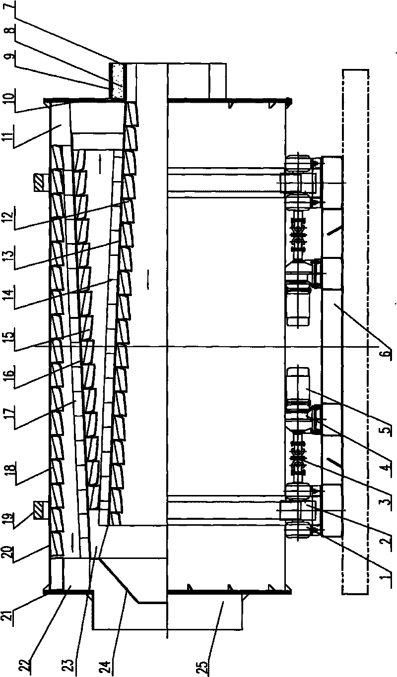
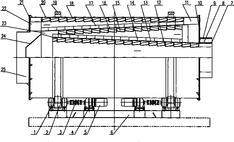
[0010] The dry-mixed mortar station three-cylinder dryer of the present invention is mainly composed of a feed pipe, a drying cylinder, a discharge pipe, and a rotary drive device. The feed pipe is a cylindrical structure, which is composed of an inner steel pipe 7, an aluminum silicate insulation layer 8 and an outer steel pipe 9. The inner steel pipe 7 and the outer steel pipe 9 are combined together, and the aluminum silicate insulation layer 8 is arranged between the inner and outer steel pipes. Those are fastened together and welded on the right end side plate 10 of the drying cylinder; the inner through hole centerline of the inner steel pipe 7 is the same axis as the rotation centerline of the drying cylinder. The drying cylinder includes an outer cylinder body 20, the two sides of the outer cylinder body 20 are connected with a feed pipe and a...


PUM


Abstract

The invention relates to a three-cylinder dryer of a dry-mixed mortar station, which comprises a drying cylinder, a feeding pipe, a discharging pipe and a rotary driving device, wherein the drying cylinder comprises an outer cylinder body, a conical middle cylinder body and a conical inner cylinder body, and inner lifting boards with columnar curved surfaces which are arranged spirally are formed on inner walls of the outer cylinder body, the conical middle cylinder body and the conical inner cylinder body respectively; a bottom board which is in the shape of a truncated cone is welded at the small end of the conical middle cylinder body, and the bottom board is fixed with a left side board of the drying cylinder and the left inner end of the outer cylinder body together through a plurality of arc-shaped blade-shaped connecting material guide boards II; the big end of the conical middle cylinder body is welded with a right side board of the drying cylinder and the right inner end of the outer cylinder body together through a plurality of arc-shaped blade-shaped connecting material guide boards I; and the small end of the conical inner cylinder body is welded on the right side board of the drying cylinder, and the big end of the conical inner cylinder body is fixedly connected with the interior of the bottom board of the middle cylinder body together through a plurality of arc-shaped blade-shaped connecting material guide boards III. The three-cylinder dryer has compact structure and high drying efficiency.

Description

technical field [0001] The invention relates to a three-cylinder dryer for a dry-mixed mortar station, and is especially suitable for drying cold sand materials in the dry-mixed mortar station. Background technique [0002] The dryer is a device specially used to dry cold sand in the dry-mixed mortar station. Its performance is directly related to the full utilization of heat energy and the quality of the finished dry-mixed mortar. The drying and cooling drum in the currently used three-cylinder dryer adopts a three-layer concentric cylindrical cylindrical structure. Although this structure can complete the drying operation of cold sand materials, it has the following shortcomings: (1) due to the use of three-layer concentric The cylindrical structure, the flow state of the sand material in it is not conducive to sufficient heat exchange with the heat flow, and the drying efficiency is not high; (2) The flow of the sand material in the cylinder is completely driven by the li...

Claims


Application Information

Patent Timeline
Patent Type & Authority Applications(China)
IPC IPC(8): F26B11/06F26B25/16F26B25/04
Inventor 孙益群杜兆阳官应旺范天锦耿欢欢
Owner 徐州沃土资产管理有限公司
Why Eureka
Try Eureka