Method of making wafer structure for backside illuminated color image sensor

a technology of color image sensor and wafer structure, which is applied in the direction of electrical equipment, semiconductor devices, radio frequency control devices, etc., can solve the problem that different wavelengths of radiation to be sensed experience different effective absorption depths in the substra

Inactive Publication Date: 2007-11-15
TAIWAN SEMICON MFG CO LTD
View PDF41 Cites 37 Cited by
  • Summary
  • Abstract
  • Description
  • Claims
  • Application Information

AI Technical Summary

Problems solved by technology

A problem with backside illuminated sensors is that different wavelengths of rad...

Method used


Image

  • Method of making wafer structure for backside illuminated color image sensor
  • Method of making wafer structure for backside illuminated color image sensor
  • Method of making wafer structure for backside illuminated color image sensor

Examples


Embodiment Construction

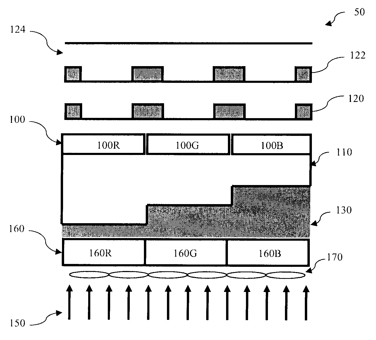
[0011]It is to be understood that the following disclosure provides many different embodiments, or examples, for implementing different features of various embodiments. Specific examples of components and arrangements are described below to simplify the present disclosure. These are, of course, merely examples and are not intended to be limiting. In addition, the present disclosure may repeat reference numerals and / or letters in the various examples. This repetition is for the purpose of simplicity and clarity and does not in itself dictate a relationship between the various embodiments and / or configurations discussed. Moreover, the formation of a first feature over or on a second feature in the description that follows may include embodiments in which the first and second features are formed in direct contact, and may also include embodiments in which additional features may be formed interposing the first and second features, such that the first and second features may not be in d...


PUM


Abstract

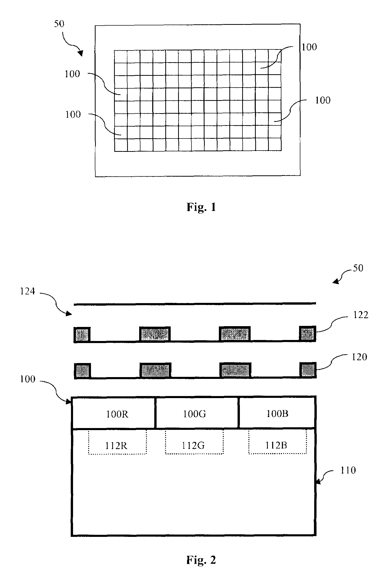
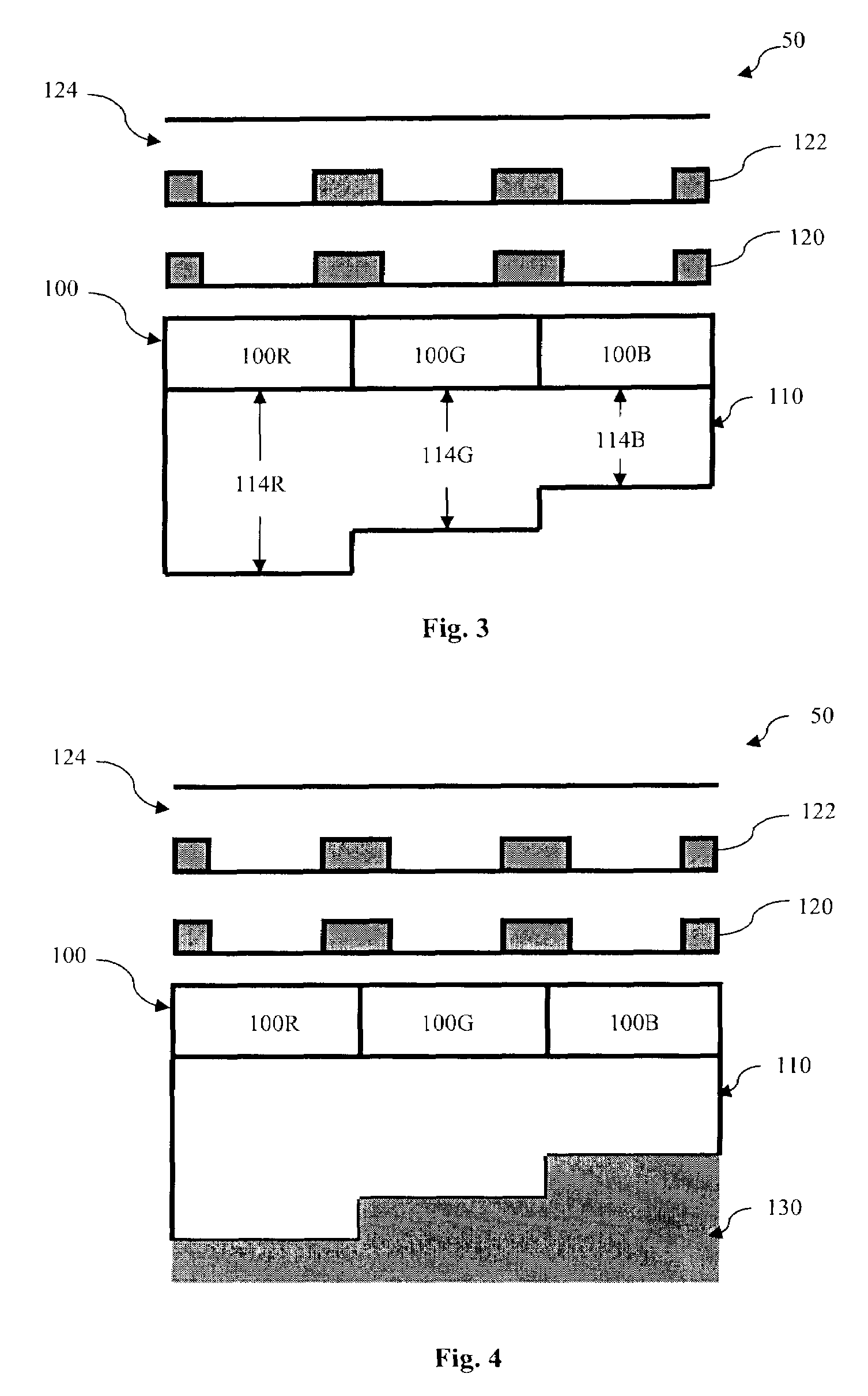
A backside illuminated sensor includes a semiconductor substrate having a front surface and a back surface, and a plurality of pixels formed on the front surface of the semiconductor substrate. The sensor further includes a plurality of absorption depths formed within the back surface of the semiconductor substrate. Each of the plurality of absorption depths is arranged according to each of the plurality of pixels. A method for forming a backside illuminated includes providing a semiconductor substrate having a front surface and a back surface and forming a first, second, and third pixel on the front surface of the semiconductor substrate. The method further includes forming a first, second, and third thickness within the back surface of the semiconductor substrate, wherein the first, second, and third thickness lies beneath the first, second, and third pixel, respectively.

Description

PRIORITY DATA[0001]This application claims the benefit of U.S. Provisional Application Ser. No. 60 / 798,876 entitled “METHOD FOR MAKING WAFER STRUCTURE FOR BACKSIDE ILLUMINATED COLOR IMAGE SENSOR,” filed May 9, 2006.BACKGROUND[0002]This application is related to U.S. Application Ser. No. 60 / 695,682 filed Jun. 30, 2005, which is hereby incorporated by reference.[0003]An image sensor provides a grid of pixels, such as photosensitive diodes or photodiodes, reset transistors, source follower transistors, pinned layer photodiodes, and / or transfer transistors for recording an intensity or brightness of light. The pixel responds to the light by accumulating a charge—the more light, the higher the charge. The charge can then be used by another circuit so that a color and brightness can be used for a suitable application, such as a digital camera. Common types of pixel grids include a charge-coupled device (CCD) or complimentary metal oxide semiconductor (CMOS) image sensor.[0004]Backside ill...

Claims


Application Information

Patent Timeline
IPC IPC(8): H01L31/113H01L31/062
CPCH01L27/1203H01L27/14621H01L27/14627H01L27/14645H01L27/1464H01L27/14689H01L27/148H01L31/18H01L27/1461H01L27/14685
Inventor HSU, TZU-HSUANHSIEH, CHRISYAUNG, DUN-NIANYU, CHUNG-YI
Owner TAIWAN SEMICON MFG CO LTD
Why Eureka
Try Eureka