
Intravenous catheter anchoring device

a catheter and anchoring technology, applied in the direction of intravenous devices, catheters, infusion needles, etc., can solve the problems of difficult catheter attachment, difficult to fix the catheter, and requiring precise, two-handed manipulation

Inactive Publication Date: 2007-11-15
VENETEC INT INC
View PDF19 Cites 46 Cited by
  • Summary
  • Abstract
  • Description
  • Claims
  • Application Information

AI Technical Summary

Benefits of technology

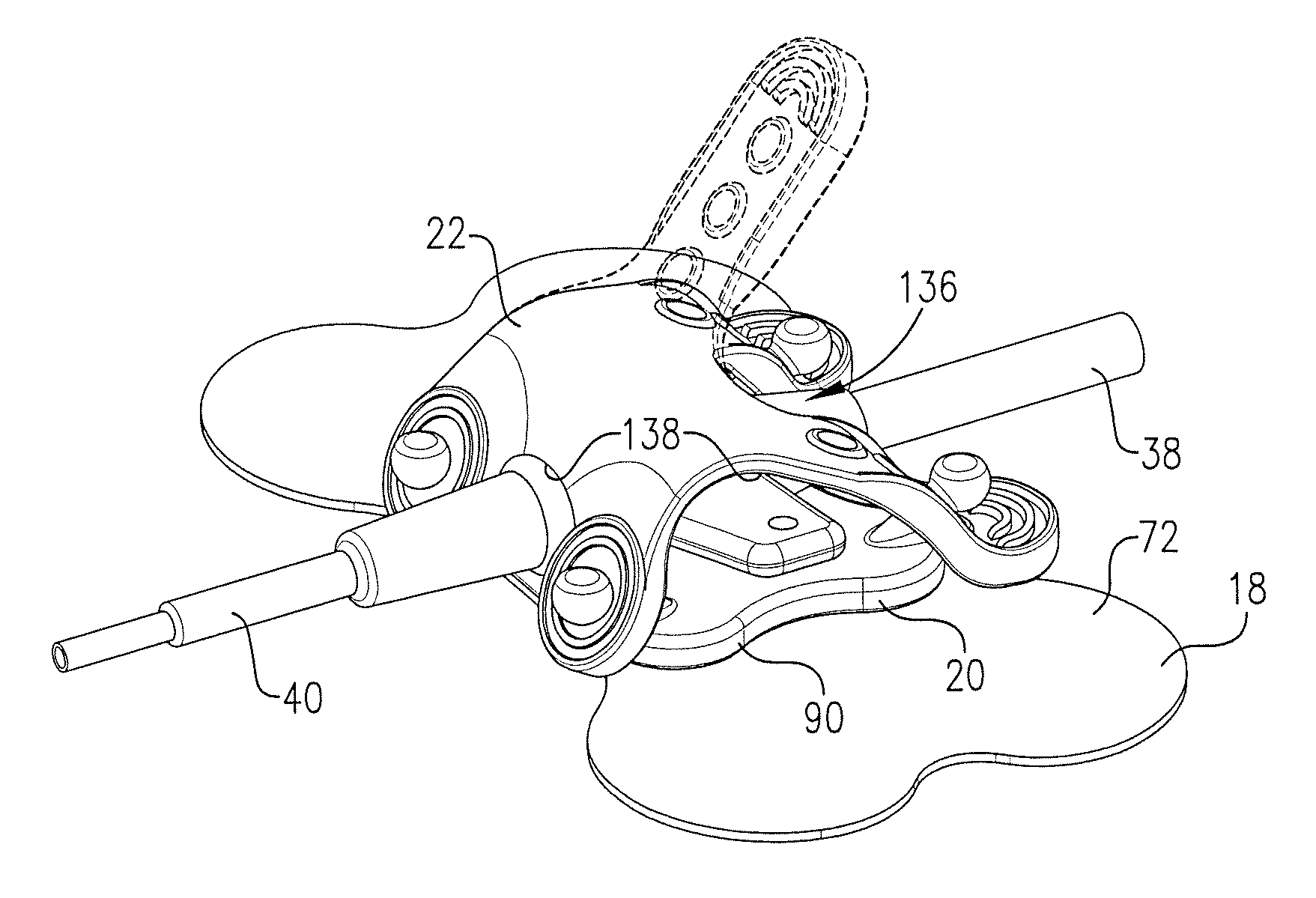
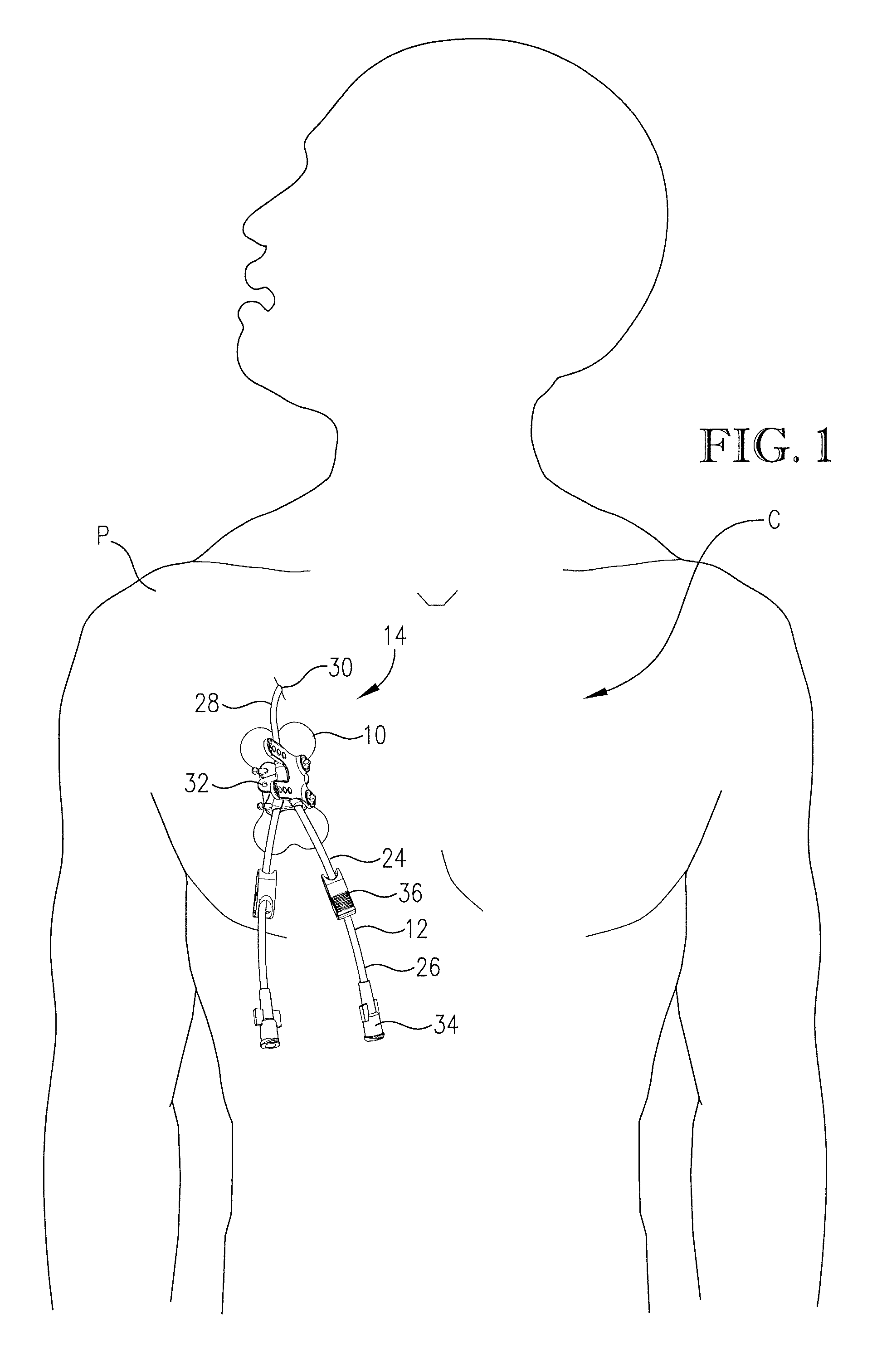
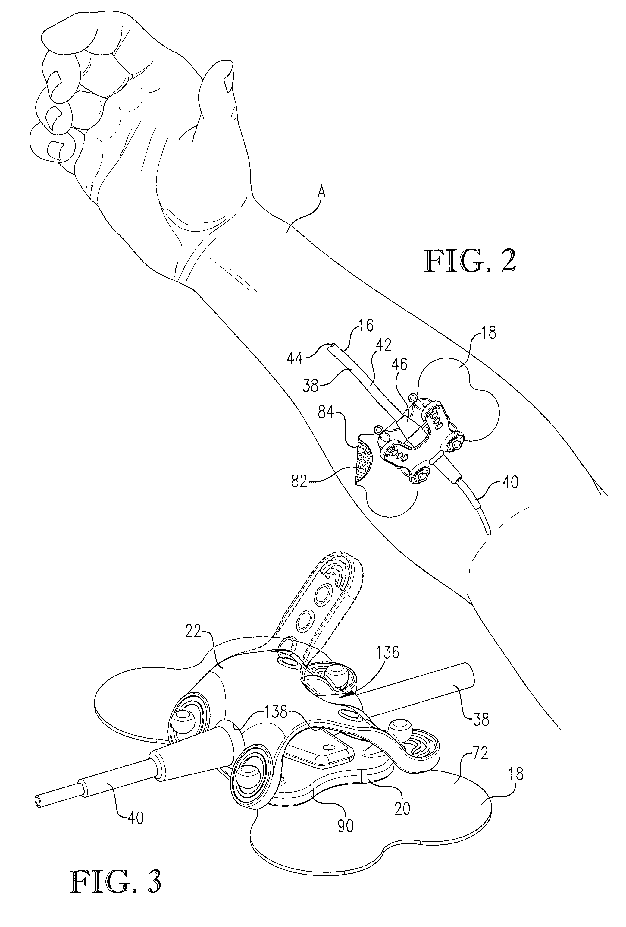
[0012] A third aspect of the present invention concerns an intravenous catheter anchoring device for securing a catheter to a patient, wherein the catheter includes a distal section configured to be at least partially inserted into the patient and a proximal section. The device broadly includes a platform configured for removable attachment to the patient and a retaining strap. The retaining strap cooperates with the platform to define a plurality of non-aligned catheter-receiving passageways, each being configured to receive a portion of the catheter with the proximal and distal sections projecting outwardly therefrom. The passageways cooperatively provide multiple catheter orientations relative to the device. The platform and strap are intercoupled at more than two coupling locations. The platform and strap cooperatively define a plurality of catheter-receiving openings, each of which is between adjacent ones of the coupling locations. Each of the passageways extends between a corresponding pair of catheter-receiving openings.

Problems solved by technology

For example, a catheter that dispenses medicine to an internal organ often must have its tip positioned in a particular location or the medicine will not have its intended effect.
Moreover, patients with these catheters often want or need to have a normal range of body motion while the catheter is inserted.
However, these anchoring devices are problematic and suffer from various undesirable limitations.
One limitation for site securement devices with tape or sutures holding the catheter in place is that they tend to start or promote infections at that location.
Furthermore, these securement devices often are able to receive only one size and shape of catheter hub (e.g., a suture hub, Y-site hub, or luer fitting).
One limitation for anchoring devices in general is that catheter attachment is difficult, requiring precise, two-handed manipulation.
Anchoring devices are also problematic because they can be inadvertently pulled from the skin's surface.
Another limitation is that anchoring devices are not adapted for use with a variety of catheter sizes and shapes.

Method used


Image

  • Intravenous catheter anchoring device
  • Intravenous catheter anchoring device
  • Intravenous catheter anchoring device

Examples


second embodiment

[0083] In FIG. 8, the present invention is an intravenous catheter anchoring assembly 200 including an alternative platform 202. The platform 202 includes a base 204 presenting an upper surface 206 and connectors 208. The base 204 further includes rib-like protrusions 210 forming part of the upper surface 206. The protrusions 210 are parallel to each other and extend between primary attachment sides 212 of the platform 202 for securing the catheter (not shown) therebetween. The protrusions 210 are preferably molded with the rest of the base 204, but could alternatively be machined or separately formed and then attached without departing from the principles of the present invention.

third embodiment

[0084] In FIG. 9, the present invention is an intravenous catheter anchoring assembly 300 including an alternative platform 302. The platform 302 includes a base 304 presenting an upper surface 306 and connectors 308. The base 304 further includes a concave depression 310 defining a curvilinear portion of the upper surface 306. The shape of the depression 310 is preferably configured to receive the catheter hub (not shown). While the illustrated depression 310 is shaped to receive a variety of catheter hubs, the depression 310 could be alternatively shaped to receive a particular catheter hub so that the depression 310 is form-fitting. The depression 310 is preferably molded with the rest of the base 304 but could also be machined or separately formed and then attached to the upper surface 306.

[0085]FIGS. 10-14 illustrate several alternative embodiments of the present invention. These alternative embodiments are directed to anchoring assemblies incorporating alternative retaining st...

fourth embodiment

[0086] In FIG. 10, the present invention is an intravenous catheter anchoring assembly 400 including an alternative retaining strap 402. The retaining strap 402 comprises a body 404 including pull-tabs 406 and presenting upper and lower surfaces 408,410. The body 404 further includes a spherical protrusion 412 forming part of the lower surface 410. The protrusion 412 is shaped to press against the catheter hub (not shown) when the retaining strap 402 is coupled to the platform (not shown). The protrusion 412 is preferably compressible to the extent that it is compressed during use of the assembly 400, whereby gripping of the catheter is further enhanced.


PUM


Abstract

An intravenous catheter anchoring assembly is disclosed and includes a patient-contacting membrane, a platform, and a retaining strap for securing a catheter or tubing of an administration set to a patient. The strap is attached to the platform with adjustable pull-tabs that permit a variety of catheter shapes and sizes to be secured. The strap is also elastomeric so that the strap is stretchable and thereby grabs the secured catheter. The strap and platform further define a plurality of passageways that permit the catheter to be secured in a plurality of non-aligned directions.

Description

CROSS REFERENCE TO RELATED APPLICATION [0001] This is a continuation-in-part of application Ser. No. 11 / 306,289 filed Dec. 21, 2005, entitled INTRAVENOUS CATHETER ANCHORING DEVICE, which is hereby incorporated by reference herein.BACKGROUND OF THE INVENTION [0002] 1. Field of the Invention [0003] The present invention relates generally to the field of intravenous infusion site devices. More specifically, the present invention concerns an intravenous catheter anchoring device for the securement of catheters on various patient sites. [0004] 2. Discussion of Prior Art [0005] Catheters for intravenous infusion into a patient are well known in the art. Such catheters are generally used in a variety of infusion applications and on a variety of sites. For example, catheters are commonly used as central venous catheters (“CVC”), midline catheters, or peripherally inserted central catheters (“PICC”). These catheters normally are used with some sort of a catheter anchoring device for attachin...

Claims


Application Information

Patent Timeline
Patent Type & Authority Applications(United States)
IPC IPC(8): A61M25/02
CPCA61M25/02A61M2025/0253A61M2025/0246A61M2025/024
Inventor SMITH, LARRY C.WINSOR, CHRIS
Owner VENETEC INT INC
Learn More