Dental syringe

a syringe and dental technology, applied in the field of dental syringes, can solve the problems of high degree of imprecision in the manner of dispensing the medication, difficult process to control the precise amount of medication, and common measurement procedures that are often difficult and time-consuming

Inactive Publication Date: 2007-11-15
ALGEN & KLEMER
View PDF21 Cites 51 Cited by
  • Summary
  • Abstract
  • Description
  • Claims
  • Application Information

AI Technical Summary

Problems solved by technology

However, due to the nature of dental injections, it is typically a difficult process to control the precise amount of medication that is dispensed by the dentist into the patient.
However, this manner of dispensing the medication has a high degree of imprecision since the dentist is judging the amount of the dose based on the degree that the plunger is advanced within the body.
However, this common measurement procedure can often be difficult and time-consuming, and more importantly, can be quite wasteful, as a quantity of the medication is often discarded in order to achieve the appropriate dosage.
Quite often, medical professionals, such as dentists, administering an injection may not have a clear view of the targeted body part of the patient, e.g., a gum portion surrounding a target tooth.
In this case, many rely on their experience to administer the desired dosage, which still may not be precise administering technique.

Method used


Image

  • Dental syringe
  • Dental syringe
  • Dental syringe

Examples


first embodiment

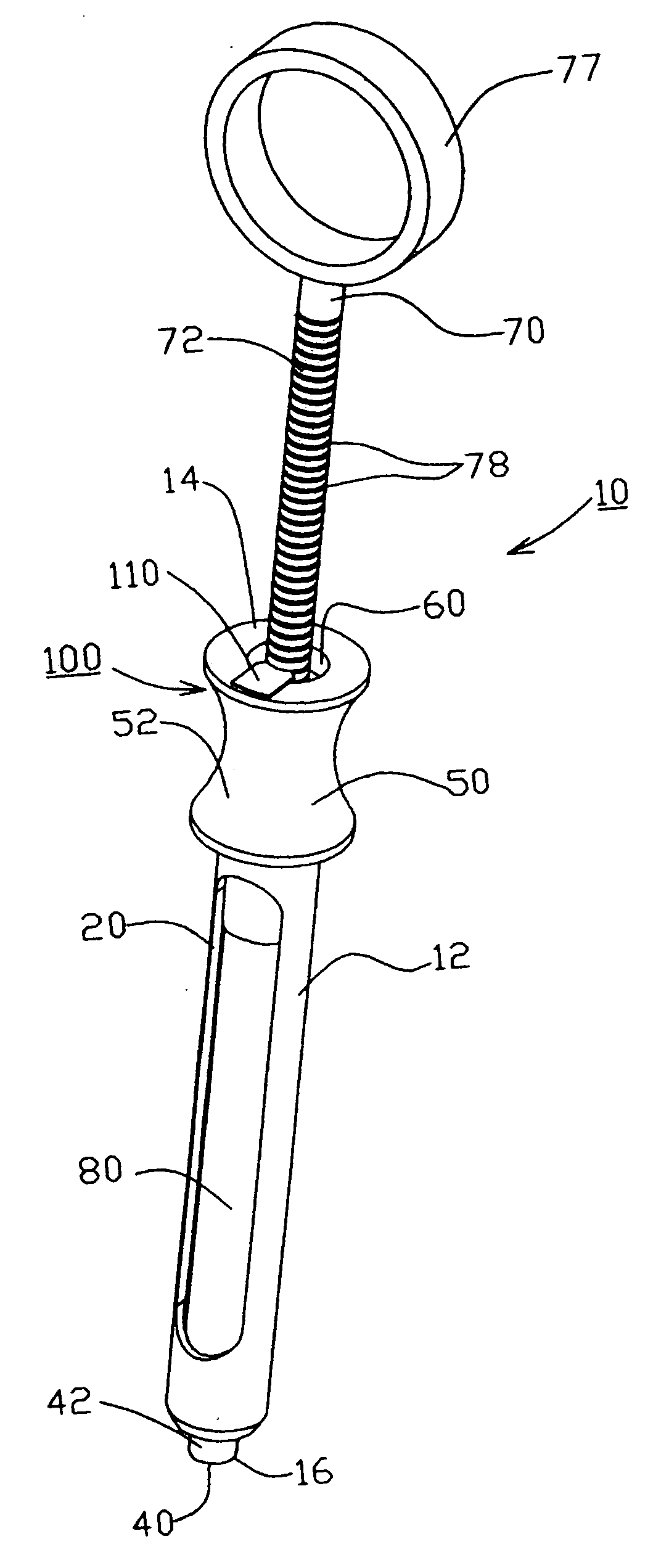
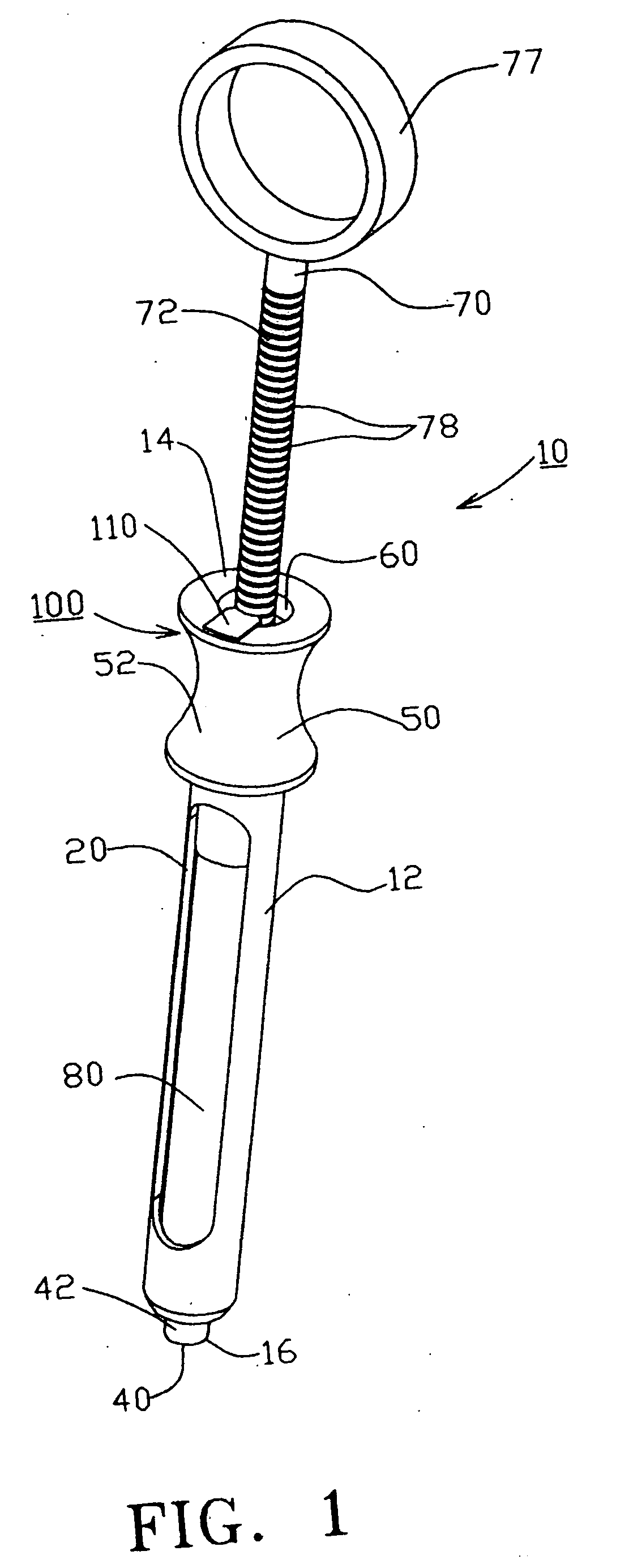
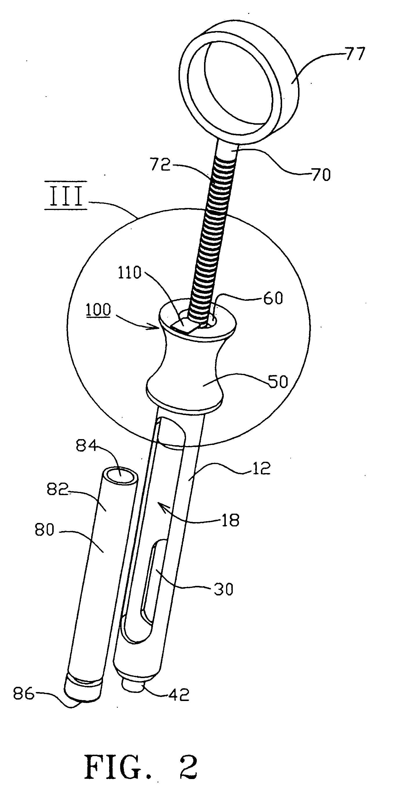
[0037] In accordance with the present invention, a dosage dispensing feature, generally indicated at 100, is provided to accurately dispense a predetermined dosage amount based on the controlled advancement of the plunger 70 within the interior 18 of the body 12. The dosage dispensing feature 100 is in the form of a flexible flange or finger 110 that extends at least partially into the opening 60 formed at the proximal end 14 of the syringe body 12. Thus, one end 112 of the flexible flange 110 is located within the opening 60, with the opposite end 114 being securely coupled to the body 12 to permit the flange 110 to flex (upwardly and downwardly) at the end 112. The illustrated flange 110 has a generally rectangular shape and is formed of a material that permits the flange 110 to flex under an applied force and then return to the rest position once the applied force is removed. For example, the flange 110 can be formed of a rigid plastic material or other material that offers the ...

second embodiment

[0042] Turning now to FIGS. 4-5 in which a dental syringe 200 is illustrated. The dental syringe 200 is similar to syringe 10 of FIGS. 1-3 and therefore, like elements are numbered alike.

[0043] The main difference between the dental syringe 10 and the dental syringe 200 is with the dosage dispensing feature and more specifically, the dental syringe 200 has a different type of dosage dispensing feature 210 for controllably dispensing a predetermined amount of medication as the plunger 70 is incrementally advanced within the body 12. In this second embodiment, the dosage dispensing feature 210 is selectively placed in an active position where it can engage the plunger 70 as shown in FIG. 4 or the dosage dispensing feature 210 can be placed into an inactive, disengaged position where it is offset from the plunger 760 and is prevented from engaging the plunger 70.

[0044] Similar to the dosage dispensing feature 100, the dosage dispensing feature 210 is in the form of an elongated flang...


PUM


Abstract

According to one exemplary embodiment of the present invention, a dental syringe includes a barrel extending along a longitudinal axis and including an interior space and a longitudinal window formed in a side wall of the barrel for receiving a cartridge that contains medication. A flexible flange member is formed at a proximal end of the barrel with one end of the flexible flange member extending into an opening at the proximal end that forms an entrance into the interior space of the barrel. The dental syringe has a plunger received in and axially displaceable within the interior space, with the plunger having a plurality of spaced grooves provided on an outer surface thereof. The flange is configured to selectively engage the grooves while generating an indicating signal corresponding to a predetermined dosage of medication dispensed from the cartridge during axial displacement of the plunger as the flange engages successive grooves.

Description

TECHNICAL FIELD [0001] The present invention relates to dispensing devices, and more particularly, the present invention relates to a dental syringe for administering a predetermined dosage of medication to a patient. DESCRIPTION OF THE RELATED ART [0002] A conventional dental syringe is formed of a metal body and a metal plunger that is slidably received within a portion of the body for administering the medication. The medication is contained within a disposable cartridge that is inserted through an opening formed in the body and is held in place within the body below the plunger. Once the cartridge is contained and held within the body, the plunger engages the cartridge to lock it in place and advancement of the plunger in an axial direction causes a force to be applied to the cartridge to cause the medication to be discharged from the cartridge through the syringe body and needle. [0003] However, due to the nature of dental injections, it is typically a difficult process to cont...

Claims


Application Information

Patent Timeline
Patent Type & Authority Applications(United States)
IPC IPC(8): A61M5/00
CPCA61C5/062A61M5/24A61M5/31501A61M5/31505A61M2205/582A61M5/31573A61M5/3158A61M5/31595A61M2205/581A61M5/3155A61M2005/2414A61C5/62
Inventor KLEYMAN, GENNADYMERSON, ALEXANDER
Owner ALGEN & KLEMER
Why Eureka
Try Eureka