Electrical intramedullary nail system

a technology of intramedullary nail and electric field, applied in the field of intramedullary nail system, can solve the problems of tissue-displacing supporting implants, affecting the biomechanical quality of supporting structures, and affecting the recovery of biological processes

Active Publication Date: 2007-11-15
NEUE MAGNETODYN
View PDF16 Cites 36 Cited by
  • Summary
  • Abstract
  • Description
  • Claims
  • Application Information

AI Technical Summary

Benefits of technology

[0008] The invention is based on the object of improving a generic intramedullary nail system particularly as regards its handling conveni

Problems solved by technology

Problematic with a rigid fixation by comparatively unelastic, tissue-displacing supporting implants is, however, the hinderance to biological recuperation particularly due to the loss of blood vessels and nerves.
Apart from this, the longer the implantation duration the more the biomechanical quality of the supporting structure suffers due to t

Method used


Image

  • Electrical intramedullary nail system
  • Electrical intramedullary nail system
  • Electrical intramedullary nail system

Examples


first embodiment

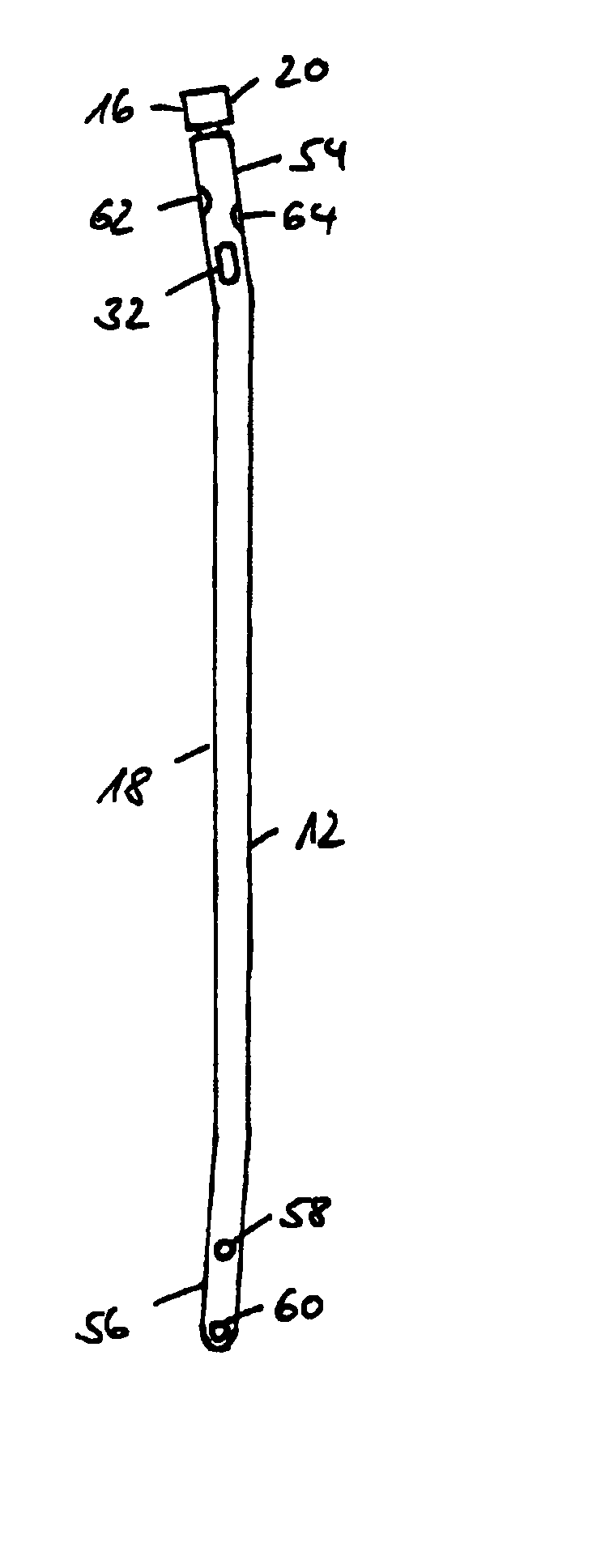
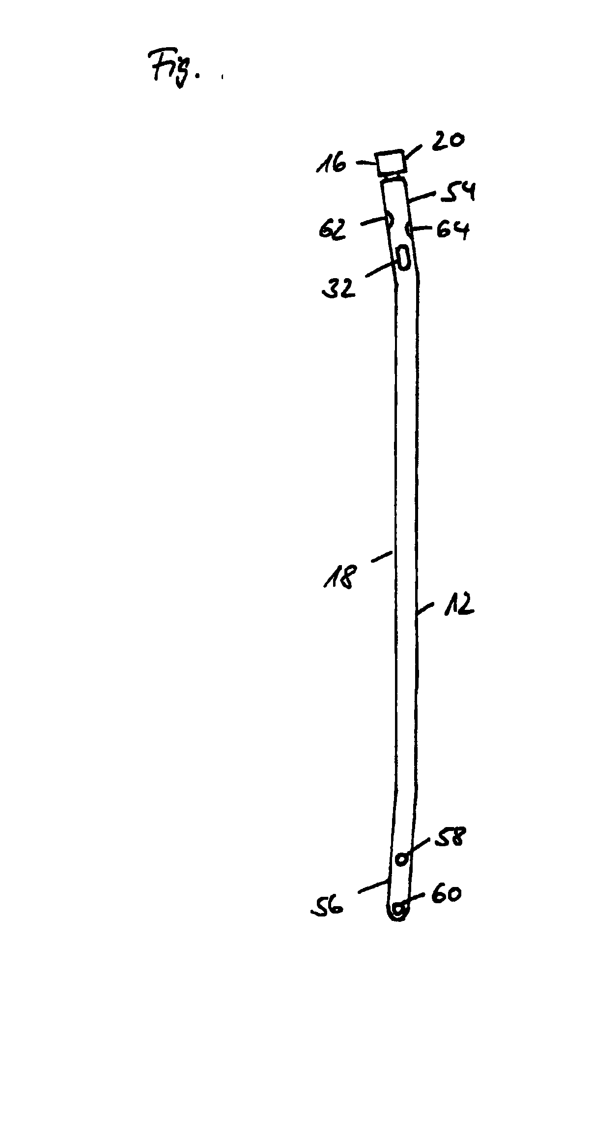
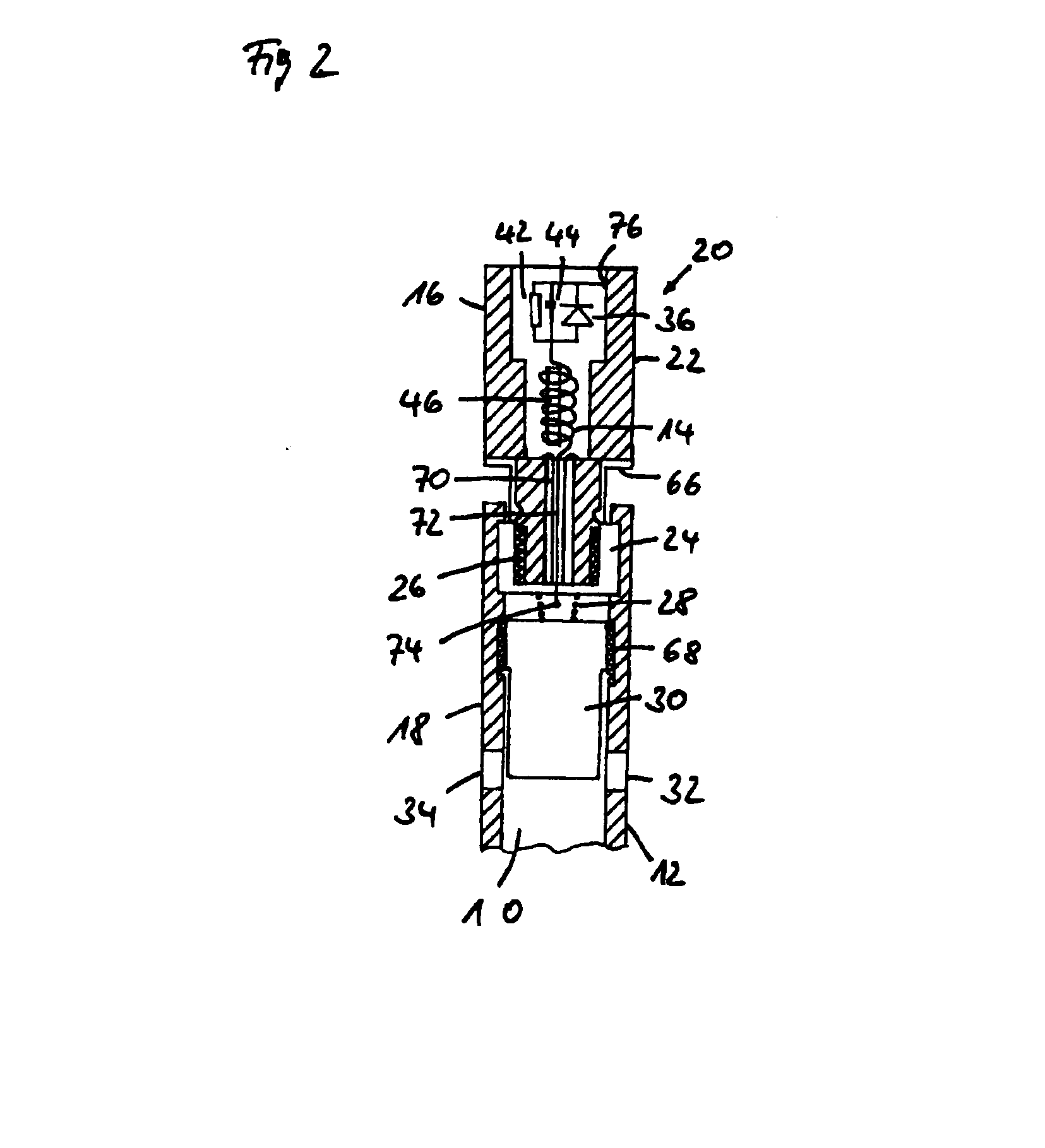
[0038] Referring now to FIG. 1 there is illustrated a side view of an intramedullary nail system in accordance with the invention; FIG. 2 showing a section taken axially through the proximal end portion of an intramedullary nail system in accordance with the invention. Illustrated is an intramedullary nail system for stabilizing and resting fragments of a broken bone for example of the tibia, the femur or humerus. The intramedullary nail system comprises a more or less cylindrical nail member 12 and an end cap assembly 20 closing off an opening of the nail member 12 at its proximal end 54 substantially axially symmetrically. The nail member 12 has at its distal end 56 likewise an opening (not shown). The openings at the proximal end 54 and distal end 56 are connected to each other by a cavity 10 in the nail member 12. Provided in the wall of the nail member are locking apertures 58, 60, 62, 64 each of which faces a further locking aperture diametrally opposed. The one group of locki...

second embodiment

[0041] Referring now to FIG. 3 there is illustrated an axial section through the proximal end portion of an intramedullary nail system in accordance with the invention wherein, unlike the embodiment as shown in FIG. 2, an end cap housing 22 of an electrically insulating material, for example biologically compatible polythene is employed. The contact surface is formed by an electrically conductive cover 90 which closes off the end cap housing 22 at its proximal end. The cover 90 can be connected to the end cap housing by being bonded, screwed or clipped in place for instance. When the cover 90 is connected to the end cap housing 22 gas and fluid-tight there is no need to pot the interior of the housing, although still possible, for example for mechanical stabilization of the electrical components and connections. The insulations 24, 26, 70 insulating the end cap housing 22 from the nail member as described in conjunction with FIG. 2 can be dispensed with when an electrically insulati...


PUM


Abstract

The invention relates to an intramedullary nail system including an elongated nail member comprising a cavity and electrically conductive at least in part, a coil assembly, a first electrode connected to a first pole of the coil assembly and a second electrode connected to a second pole of the coil assembly. To improve such an intramedullary nail system particularly as regards its convenience in handling and flexible application during the operation, its stability, its biological effect, its therapeutical effectiveness and its economy it is provided for that the coil assembly is provided in an end cap assembly proximally releasably connected to the nail member with an outer contact surface being electrically conductive at least in part, that the contact surface is electrically insulated from the nail member, that at least one section of the contact surface forms the first electrode and that at least one section of the nail member forms the second electrode.

Description

CLAIM OF BENEFIT OF EARLIER FILING DATE [0001] The present application claims the benefit of the filing date of German Application No. DE 102006018191.3 (filed Apr. 19, 2006) the contents of which are hereby incorporated by reference in their entirety. TECHNICAL FIELD [0002] The invention relates to an intramedullary nail system including an elongated nail member comprising a cavity and which is electrically conductive at least in part, a coil assembly, a first electrode connected to a first pole of the coil assembly and a second electrode connected to a second pole of the coil assembly. BACKGROUND OF THE INVENTION [0003] Such intramedullary nail systems are known in the field of osteosynthesis which serves the fixation of fragments of a broken or diseased bone in its uninjured, natural form stable to loading by implanted screws, supporting plates, wires, intramedullary nails and the like which are generally made of stainless steel or titanium alloys. These osteosynthesis means perm...

Claims


Application Information

Patent Timeline
IPC IPC(8): A61B17/72
CPCA61B17/72A61N1/326A61N2/06A61N2/02A61N1/40
Inventor KRAUS, WERNERKRAUS, STEPHANIEWIEGMANN, MARKUS
Owner NEUE MAGNETODYN
Why Eureka
Try Eureka