
Internal combustion engine

Active Publication Date: 2007-11-22
YAMAHA MOTOR CO LTD +1
View PDF9 Cites 4 Cited by
  • Summary
  • Abstract
  • Description
  • Claims
  • Application Information

AI Technical Summary

Benefits of technology

[0007]Accordingly, the present invention provides an internal combustion engine that reduces adverse influences on engine components by the secondary air passage located above the combustion chamber.
[0008]A first aspect of the present invention provides an internal combustion engine that has a secondary air passage located above a combustion chamber. A water jacket is provided between the secondary air passage and an exhaust passage that communicates with the combustion chamber. According to the first aspect of the present invention, the high-temperature exhaust gas that flows in and stays in the secondary air passage is cooled down by the coolant flowing through the water jacket. Further, because of the location of the water jacket, it is possible to prevent the secondary air passage from receiving heat from the exhaust passage through which the high-temperature exhaust gas flows. Therefore, various adverse affects on components of the engine by the heat radiation from the secondary air passage are effectively reduced.
[0009]In a second aspect of the present invention, an internal combustion engine is provided that has a secondary air passage located above a combustion chamber. A water jacket is -provided between the secondary air passage and an intake passage that communicates with the combustion chamber. According to this aspect of the present invention, high-temperature exhaust gas that flows in and stays in the secondary air passage is cooled down by the coolant flowing through the water jacket. Accordingly, various adverse affects on engine components by the heat radiation from the secondary air passage can be reduced. Further, because of the location of the water jacket, heat receiving of the intake passage is reduced, and thereby effectively suppressing the increase in temperature of the intake air, in particular.
[0010]A third aspect of the present invention provides an internal combustion engine having a secondary air passage located above a combustion chamber. A water jacket is formed so as to circumscribe the secondary air passage. According to the aspect of the present invention, because of the shape of the water jacket, the high-temperature exhaust gas that flows in and stays in the secondary air passage can be effectively cooled down by the coolant flowing through the water jacket. As a result, various adverse influences on components of the engine by the heat radiation from the secondary air passage can be effectively reduced.

Problems solved by technology

In other words, such an internal combustion engine is favorable in cost However, when the afterburning of the exhaust gas is not performed, the high-temperature exhaust gas flows into and stays in the secondary air passage.
Accordingly, in such an internal combustion engine, because of its structure, heat radiation from the secondary air passage may cause various adverse affects on the components.
More specifically, for example, increase in the intake air temperature reduces volumetric efficiency of the intake air, and the output performance of the internal combustion engine may thus be reduced.
Further, when the intake air temperature increases, knocking may occur more easily.
Furthermore, for example, the temperature of a valve operating mechanism that operates an intake valve or an exhaust valve may increase, as compared to conventional structures, and reliability may thus decrease.
Further, for example, the engine oil staying above the secondary air passage may receive heat, thereby accelerating the deterioration of engine oil by heat.

Method used


Image

  • Internal combustion engine
  • Internal combustion engine
  • Internal combustion engine

Examples


Embodiment Construction

[0017]Example embodiments according to the present invention will be described with reference to the accompanying drawings.

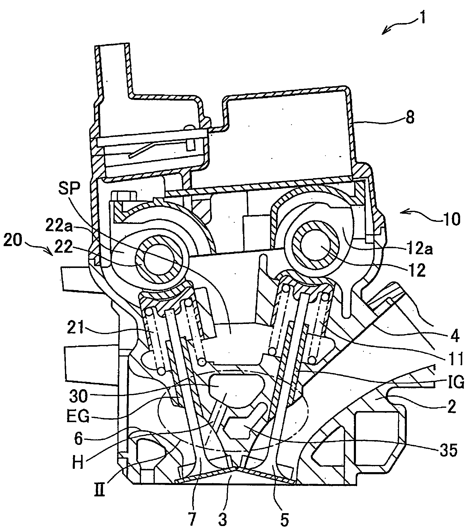
[0018]FIG. 1 is a schematic view illustrating main portions of an internal combustion engine 1 according to an example embodiment. More specifically, FIG. 1 shows a cylinder head 2 of the internal combustion engine 1 and other components related to the cylinder head 2, as the main portions of the internal combustion engine 1. Further, the internal combustion engine 1 has an inline four cylinder arrangement. In FIG. 1, main portions of a single cylinder, viewed from the axial direction of a crankshaft, is shown as a representative of cylinders. Note that the cylinder arrangement is not limited to the inline four cylinder arrangement Furthermore, in this example embodiment, both the axial direction of the crankshaft and the direction of the cylinder arrangement L are in the direction generally perpendicular to the plane of the paper on which the drawing is drawn. ...


PUM


Abstract

An internal combustion engine is provided that includes a combustion chamber, a secondary air passage located above the combustion chamber; an exhaust passage that communicates with the combustion chamber, and a water jacket that is located between the exhaust passage and the secondary air passage.

Description

INCORPORATION BY REFERENCE[0001]he disclosure of Japanese Patent Application No. 2006-136895 filed on May 16, 2006 including the specification, drawings and abstract is incorporated herein by reference in its entirety.BACKGROUND OF THE INVENTION [0002]1. Field of the Invention[0003]The present invention relates to an internal combustion engine, in particular, to an internal combustion engine that has a secondary air passage located above a combustion chamber.[0004]2. Description of the Related Art[0005]Conventionally, an internal combustion engine that has a secondary air passage is known. In such internal combustion engines, an internal combustion engine that has a secondary air passage located above a combustion chamber (see, for example JP-A-2005-248794, JP-A-2000-87739), or an internal combustion engine that has a secondary air passage extending along an exhaust passage (see, for example, JP-A-2000-73752) are known. The secondary air passage introduces secondary air into the exh...

Claims


Application Information

Patent Timeline
IPC IPC(8): F02F1/40F02B15/00
CPCF01N3/34F02D13/0207Y02T10/20F02F1/38F02F1/40F02D13/0226Y02T10/12
Inventor SHIRABE, TAKEOHAMADA, TSUNERO
Owner YAMAHA MOTOR CO LTD
Learn More