Substrate cleaning method, substrate cleaning system and program storage medium

Inactive Publication Date: 2007-11-22
TOKYO ELECTRON LTD
View PDF18 Cites 22 Cited by
  • Summary
  • Abstract
  • Description
  • Claims
  • Application Information

AI Technical Summary

Benefits of technology

[0053]The present invention has an effect on improving uniformly removing part

Problems solved by technology

Thus it is possible that particles adhering to some part of the s

Method used


Image

  • Substrate cleaning method, substrate cleaning system and program storage medium
  • Substrate cleaning method, substrate cleaning system and program storage medium
  • Substrate cleaning method, substrate cleaning system and program storage medium

Examples


first embodiment

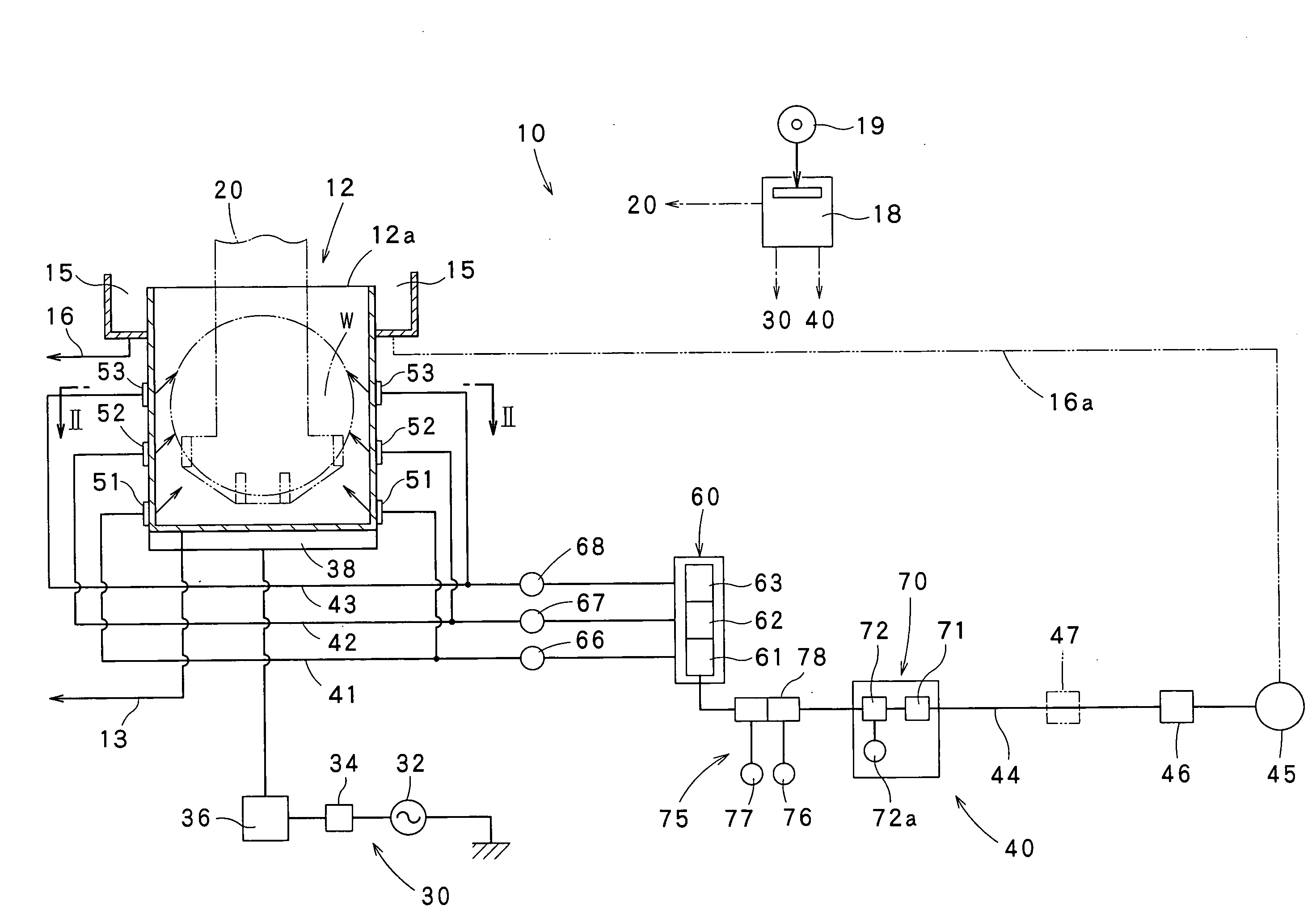
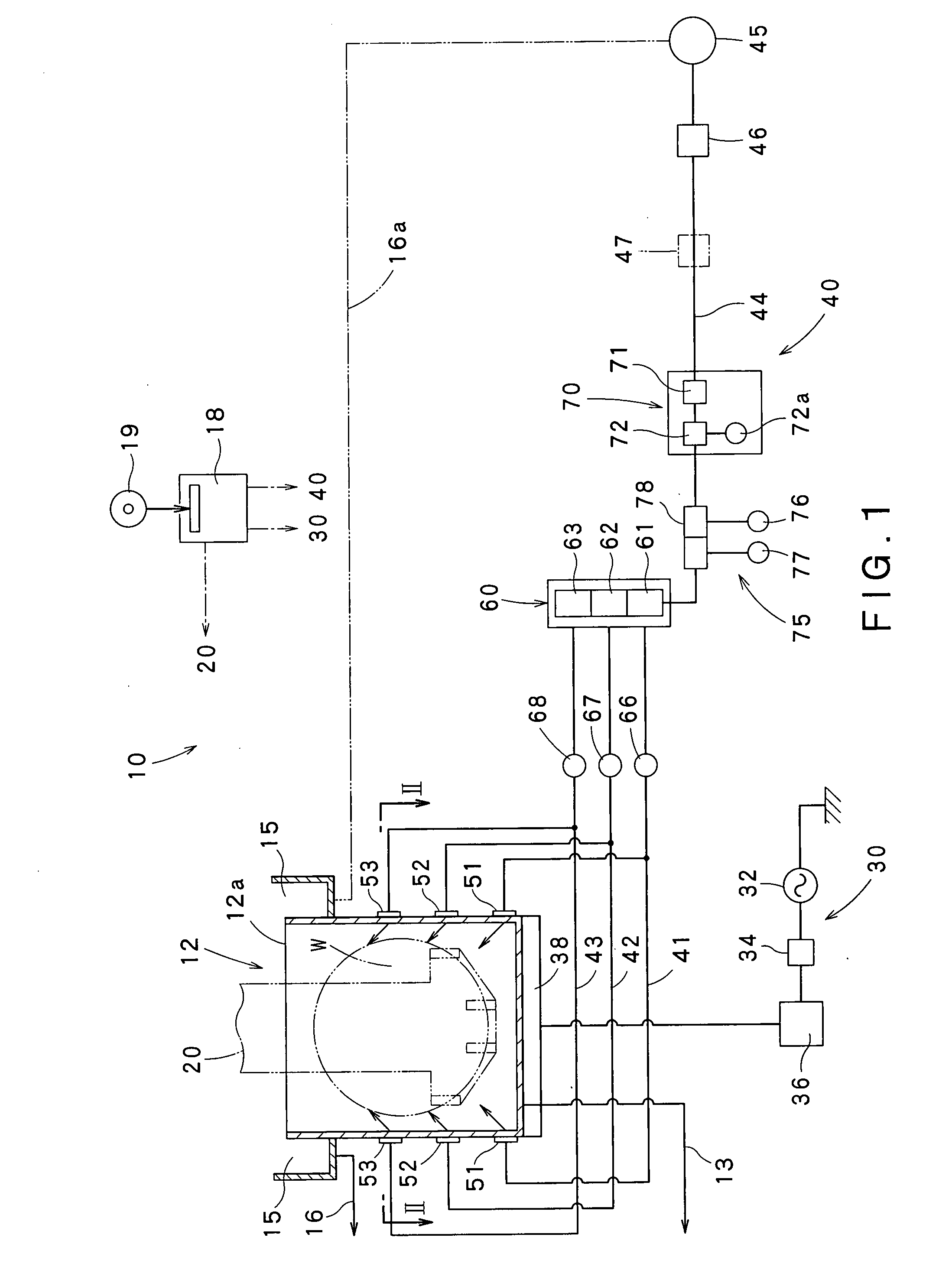
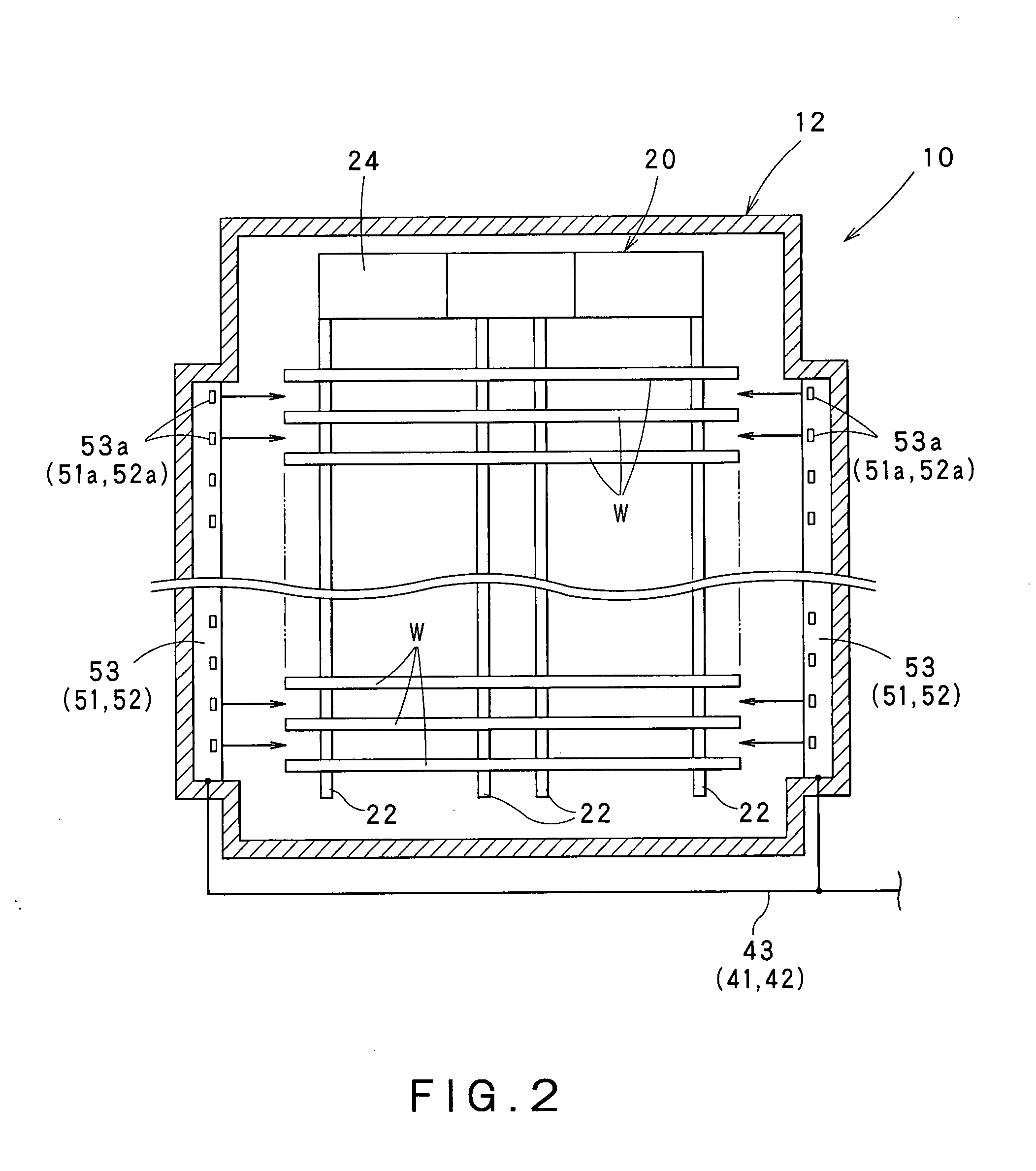
[0069]FIGS. 1 to 6 are views showing a substrate cleaning system, a substrate cleaning method, a program and a storage medium in a this embodiment according to the present invention. FIG. 1 is a schematic view of the substrate cleaning system in the first embodiment, FIG. 2 is a cross-sectional view taken on the line II-II in FIG. 1, FIG. 3 is a diagram showing an operating mode of an ultrasonic generator, and variation of a supplying rate at which a cleaning liquid is supplied into a cleaning tank and a concentration of the cleaning liquid, and FIGS. 4 to 6 are views of assistance in explaining a mode of propagation of ultrasonic waves in a cleaning liquid.

[0070]Referring to FIG. 1, a substrate cleaning system 10 in a this embodiment according to the present invention includes a cleaning tank (DIP tank) 12, a cleaning liquid supply system 40 connected to the cleaning tank 12 so as to supply a cleaning liquid into the cleaning tank 12, a wafer boat 20 for holding wafers (substrate t...

modification 1

[0135](Modification 1)

[0136]In the foregoing embodiment, the cleaning liquid is supplied sequentially through the first supplying members 51, the second supplying members 52 and the third supplying members 53 in that order. However, the present invention is not limited thereto. For example, the supplying order of the supplying members 51, 52 and 53 may be reversed.

[0137]In the foregoing embodiment, each of the first supplying members 51, the second supplying members 52 and the third supplying members 53 supply the cleaning liquid into the cleaning tank 12 in only one predetermined continuous period. However, not limited thereto, any of the first supplying members 51, the second supplying members 52 and the third supplying members 53 may supply the cleaning liquid into the cleaning tank 12 in two or more periods. For example, a cleaning liquid supplying cycle between the times t1 and t4, shown in FIG. 3, may be repeated twice.

modification 2

[0138](Modification 2)

[0139]In the foregoing embodiment, the substrate cleaning system 10 has the three pairs of supplying members, namely, the pair of first supplying members 51, the pair of second supplying members 52 and the pair of third supplying members 53. However, the structure of supplying member is not limited thereto. The number and the positions of the supplying members are not limited to those specifically described above and the number and arrangement of the supplying members may be determined taking into consideration various conditions including the size of wafers W to be cleaned.


PUM

PropertyMeasurementUnit
Concentrationaaaaaaaaaa

Abstract

A substrate cleaning method can uniformly removing particles from substrates at a high removing efficiency. The substrate cleaning method includes the steps of immersing substrates W in a cleaning liquid in a cleaning tank 12, and generating ultrasonic waves in the cleaning liquid contained in the cleaning tank. A region in the cleaning tank toward which the cleaning liquid is supplied is varied with respect to a vertical level in the step of generating ultrasonic waves in the cleaning liquid while the cleaning liquid is being supplied into the cleaning tank.

Description

CROSS REFERENCE TO RELATED APPLICATIONS[0001]This application is based upon and claims the benefit of priority from the prior Japanese Patent Application No. 2006-140377 filed on May 19, 2006, the entire contents of which are incorporated herein by reference.BACKGROUND OF THE INVENTION[0002]1. Field of the Invention[0003]The present invention relates to a substrate cleaning method and a substrate cleaning system for removing particles (foreign matters) adhering to a substrate to be cleaned by immersing the substrate in a cleaning liquid and generating ultrasonic waves in the cleaning liquid. More particularly, the present invention relates to a substrate cleaning method and a substrate cleaning system capable of removing particles from the entire surface of a substrate at a high removing efficiency.[0004]The present invention relates also to a program storage medium storing a program for accomplishing a substrate cleaning method capable of removing particles from the entire surface ...

Claims


Application Information

Patent Timeline
IPC IPC(8): B08B3/12
CPCH01L21/67057H01L21/67051H01L21/302H01L21/304
Inventor WATANABE, TSUKASASHINDO, NAOKIHIROSHIRO, KOUKICHIKAMIKAWA, YUJI
Owner TOKYO ELECTRON LTD
Why Eureka
Try Eureka