
Mobile projection device for projection mapping.

Active Publication Date: 2019-02-14
LIGOT PHILIPPE ANDRE CONSTANT
View PDF8 Cites 0 Cited by
  • Summary
  • Abstract
  • Description
  • Claims
  • Application Information

AI Technical Summary

Benefits of technology

The patent text describes a mobile projection device that can be used for low-cost projection mapping. The device is designed to meet the specifications of most projects and reduce operating costs. It is easy to install and take away, making it easier to obtain administrative approvals. Additionally, the device includes a heat removal system that improves the efficiency of the device. The light passes through the device's window with minimal light loss, resulting in improved overall efficiency.

Problems solved by technology

Nevertheless, such an installation requires hoists and a large amount of manpower in order to put up the scaffolding, and to handle, connect and then chock each projector, such that the cost of setting up an installation and taking it down represents a very significant fraction of the budget for a projection mapping project.
In addition, since each installation is unique, it is necessary, for each project, to be in a position to demonstrate that it satisfies criteria for being granted the necessary administrative authorizations, which are usually very constricting.

Method used


Image

  • Mobile projection device for projection mapping.
  • Mobile projection device for projection mapping.
  • Mobile projection device for projection mapping.

Examples


Embodiment Construction

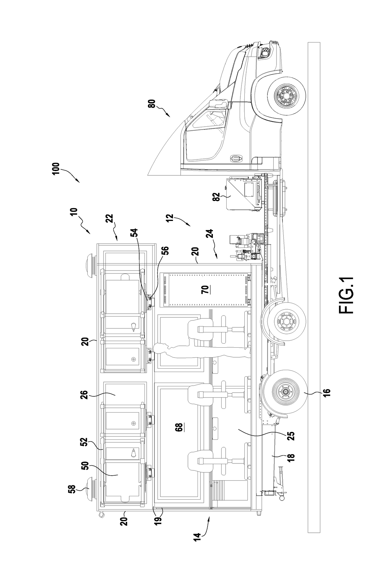
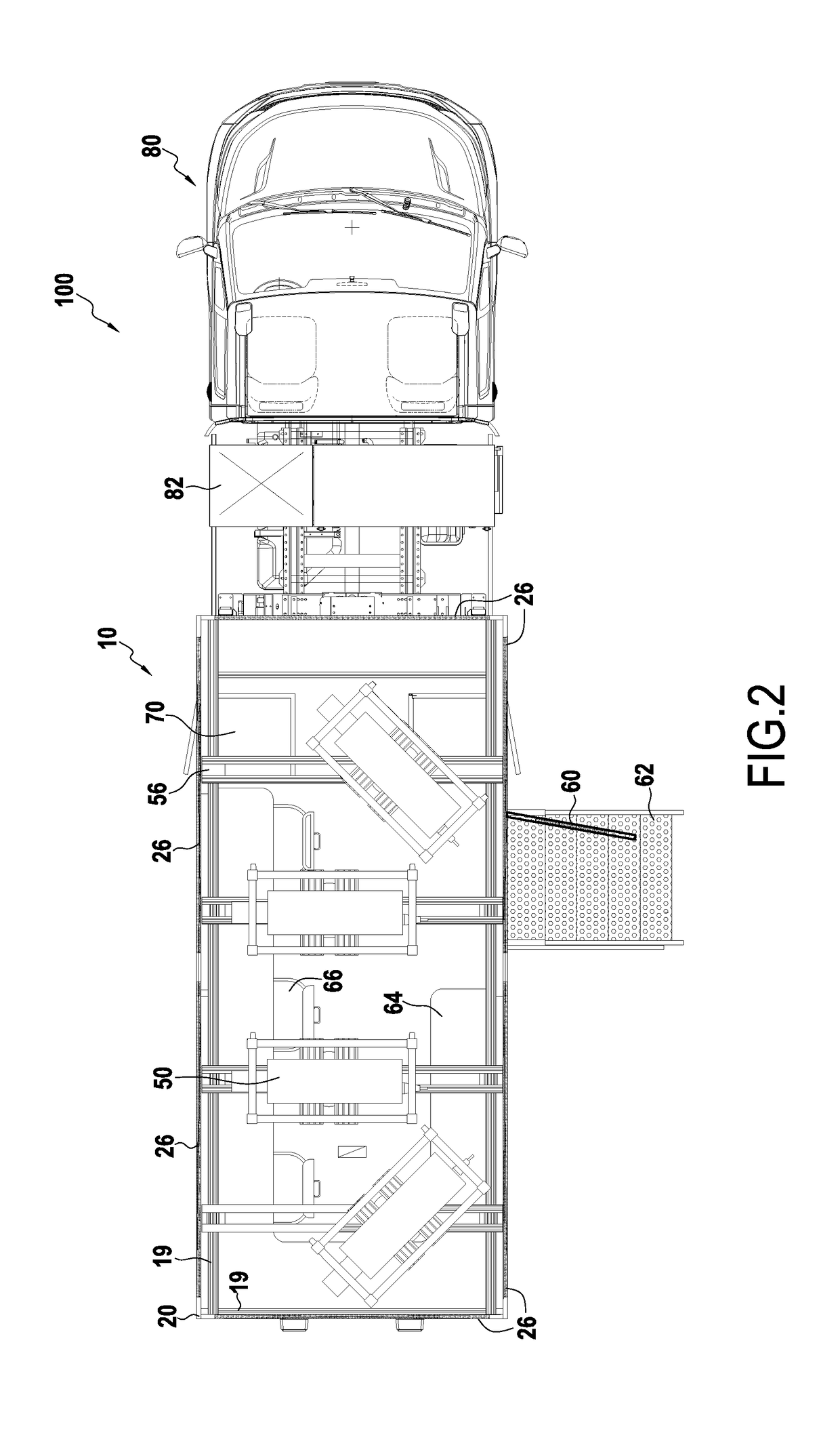
[0030]FIGS. 1 and 2 show a mobile projector set 100 in a first embodiment. In this example, the mobile projector set 100 is in the form of a truck, here a 3.5 (metric) tonne (t) truck, approved for road use under normal traffic conditions. The mobile projector set 100 comprises a mobile projection device 10 and a tractor vehicle 80 configured to tow the mobile projection device 10.

[0031]The mobile projection device 10 is specially adapted for providing projection mapping services. It comprises a road vehicle 12, in this example a trailer, and at least one light projector unit 50 configured to emit and project a light beam for projection mapping, i.e. a dynamic light beam. For instance, the trailer 12 comprises a structure 14 mounted on wheels 16, in this example via a chassis 18 with one or more axles.

[0032]The structure 14 has bars 19. In this embodiment, the bars 19 support outside walls 20, here walls that are substantially vertical or horizontal (considered relative to the gravi...


PUM


Abstract

A mobile projection device for projection mapping, the device comprising a road vehicle having a structure mounted on wheels, and at least one light projector unit mounted on the structure and configured to be controlled so as to provide projection mapping in the environment outside the mobile projection device.

Description

FIELD OF THE INVENTION[0001]The present disclosure relates to the field of spectacles, and more particularly to a mobile projection device for projection mapping.TECHNOLOGICAL BACKGROUND[0002]Projection mapping, or providing spectacle lighting to be displayed on a space, is a burgeoning activity in which dynamic light beams are used to modify the visual impression given by a monument, an inside or outside space, a landscape, etc., in order to present a spectacle, create an ambience, enhance an event, a building, illustrate an architectural or signage project, etc.[0003]Projection mapping is generally used in the context of major events for which the staging is created specifically. Each event presents particular constraints concerning the equipment, the human resources, and the logistics that are to be implemented, depending in particular on the light power required, on the type of staging that is envisaged (images that are more or less complex, stationary or moving or animated, etc...

Claims


Application Information

Patent Timeline
IPC IPC(8): G09B29/00G03B21/16
CPCG09B29/005G03B21/16B60R2011/004G01C15/00A63J5/02G03B21/54
Inventor LIGOT, PHILIPPE ANDRE CONSTANT
Owner LIGOT PHILIPPE ANDRE CONSTANT
Learn More