Method of Making a Load Bearing Member for an Elevator System

Active Publication Date: 2008-09-18
OTIS ELEVATOR CO
View PDF17 Cites 0 Cited by
  • Summary
  • Abstract
  • Description
  • Claims
  • Application Information

AI Technical Summary

Benefits of technology

[0012]In one example, the method includes heating the tension member sufficiently to cause at least partial melting of the first

Problems solved by technology

One difficulty associated with such grooves is that they tend to introduce noise and vibrati

Method used


Image

  • Method of Making a Load Bearing Member for an Elevator System
  • Method of Making a Load Bearing Member for an Elevator System
  • Method of Making a Load Bearing Member for an Elevator System

Examples


Embodiment Construction

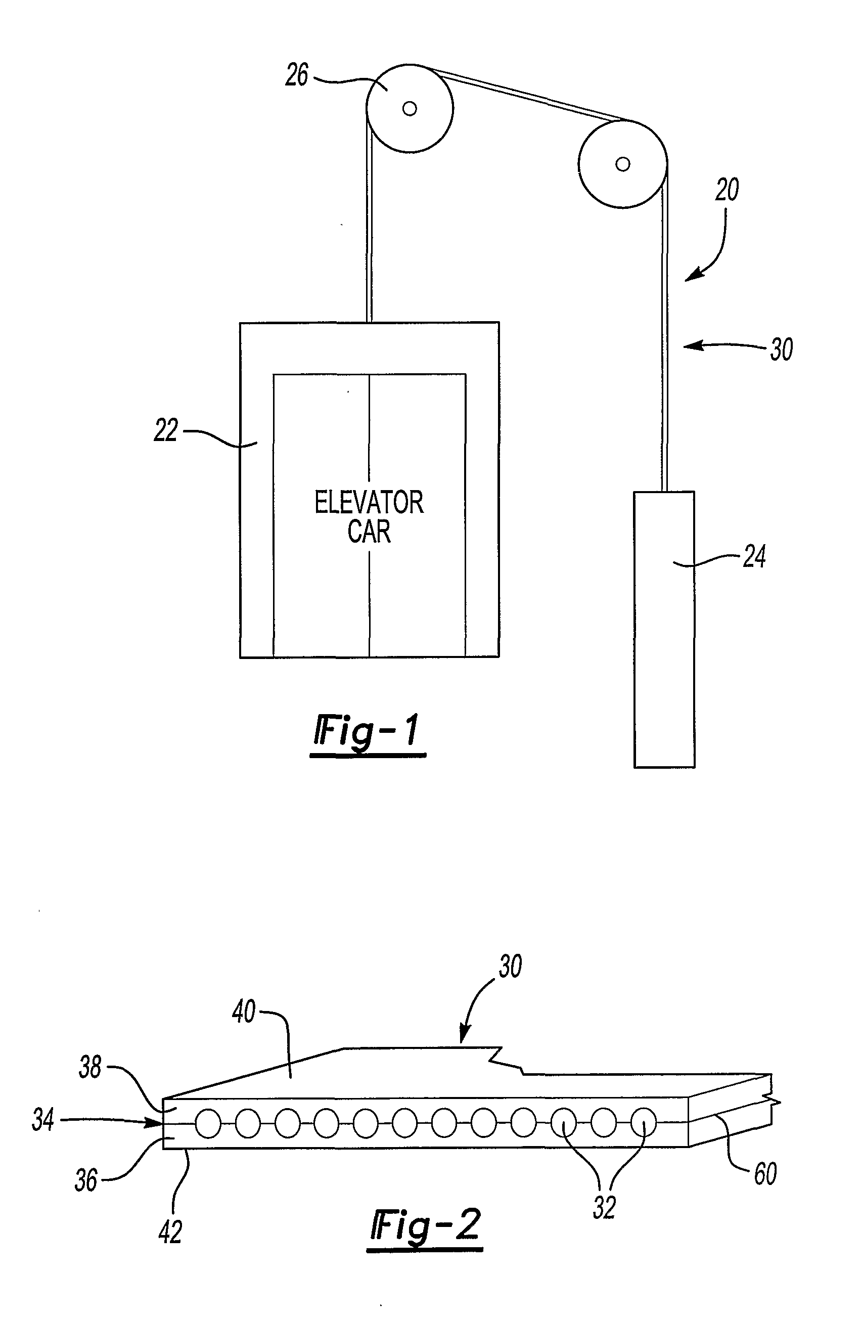
[0019]FIG. 1 schematically shows selected portions of an elevator system 20. An elevator car 22 and a counterweight 24 are suspended by a load bearing member 30. Traction between the load bearing member 30 and a traction sheave 26 allows desired movement of the elevator car 22 as known.

[0020]FIG. 2 shows an end view of one example load bearing member 30 designed according to an embodiment of this invention. In the example of FIG. 2, a plurality of tension members 32 are encased in a jacket 34 that comprises urethane. In the illustrated example, a first layer 36 comprises a polymer, which includes a urethane in some examples. Other example polymers include polypropylene and polyethylene. A second layer 38 comprises urethane in some examples. In one example, the first and second layers are different from each other in some respect. In another example, the same material is used for both layers.

[0021]The illustrated example is a flat belt. This invention is not limited to a particular g...


PUM

PropertyMeasurementUnit
Temperatureaaaaaaaaaa
Tensionaaaaaaaaaa
Frictionaaaaaaaaaa

Abstract

A method of making a load bearing member (30) for an elevator system (20) includes placing at least one tension member (32) adjacent one side (60) of a first layer (36) of a polymer material. A second layer (38), comprising a urethane in a disclosed example, is added adjacent to at least the one side (60) of the first layer (36) such that the tension member (32) is between the first layer (36) and the second layer (38). Such a technique allows for eliminating the bridges typically used to support the tension members in molding devices. Eliminating such bridges eliminates the resulting grooves associated with previous arrangements. Providing a grooveless exterior on the jacket (34) of the load bearing member (30) eliminates a significant source of potential vibration and noise in an elevator system.

Description

1. FIELD OF THE INVENTION[0001]This invention generally relates to elevator systems. More particularly, this invention relates to a load bearing member for elevator systems.2. DESCRIPTION OF THE RELATED ART[0002]There are several known types of elevator systems. Traction-based systems typically include an elevator car, a counterweight and load bearing members that support the car and counterweight. The car moves between different levels because of traction between the load bearing members and a traction sheave, for example.[0003]Elevator system load bearing members come in various forms. For many years steel ropes were used. More recently, other load bearing members have been introduced. Some examples include flat belts having a plurality of tension members encased in a urethane jacket. Some examples include steel cords as the tension members while others include aramid materials as the tension members.[0004]Regardless of the selected materials, known manufacturing methods typically...

Claims


Application Information

Patent Timeline
IPC IPC(8): B32B15/095B32B7/022
CPCB32B3/08Y10T428/2942B32B7/02B32B15/18B32B27/08B32B27/40B32B37/153B32B2305/08B32B2307/538B32B2307/54B32B2307/744B32B2419/00B66B7/062D07B2201/1008D07B2201/2088D07B2501/2007Y10T428/2938Y10T428/2947B32B3/30D07B2201/2087B32B7/022B32B37/00B66B11/08B32B5/12
Inventor O'DONNELL, HUGHGOESER, HUBERT E.
Owner OTIS ELEVATOR CO
Why Eureka
Try Eureka