Side-emitting LED light source for backlighting applications

Inactive Publication Date: 2010-09-30
KONINKLIJKE PHILIPS ELECTRONICS NV
View PDF8 Cites 1 Cited by
  • Summary
  • Abstract
  • Description
  • Claims
  • Application Information

AI Technical Summary

Benefits of technology

[0028]Thus, there is provided a method in which two sub-assemblies are first manufactured before assembling, which is advantageous as it allows for inspection of the separate sub-assemblies before mounting. If the two sub-assemblies are chosen to be identical the manufacturing

Problems solved by technology

However, the mounting of the individual side-emitting LEDs invo

Method used


Image

  • Side-emitting LED light source for backlighting applications
  • Side-emitting LED light source for backlighting applications
  • Side-emitting LED light source for backlighting applications

Examples


Embodiment Construction

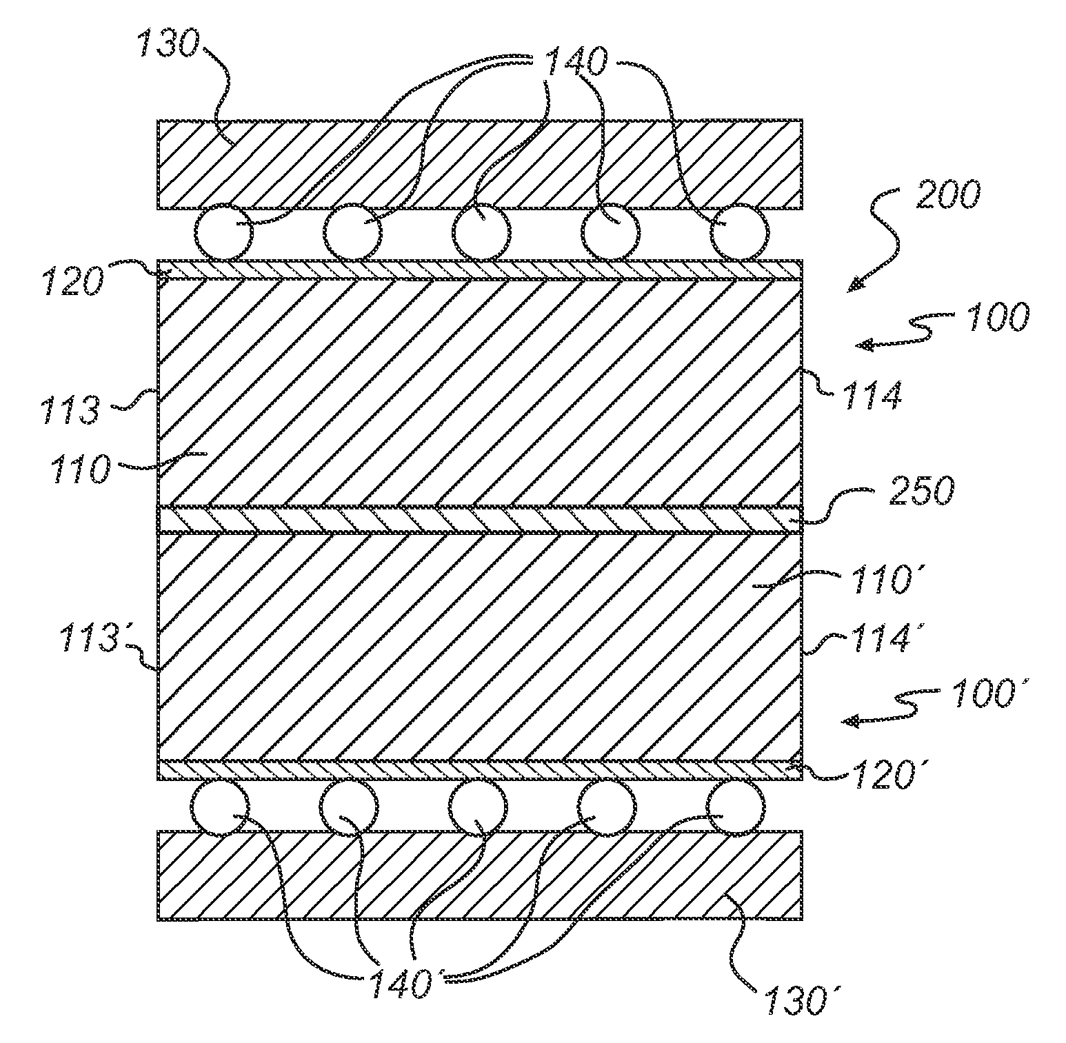
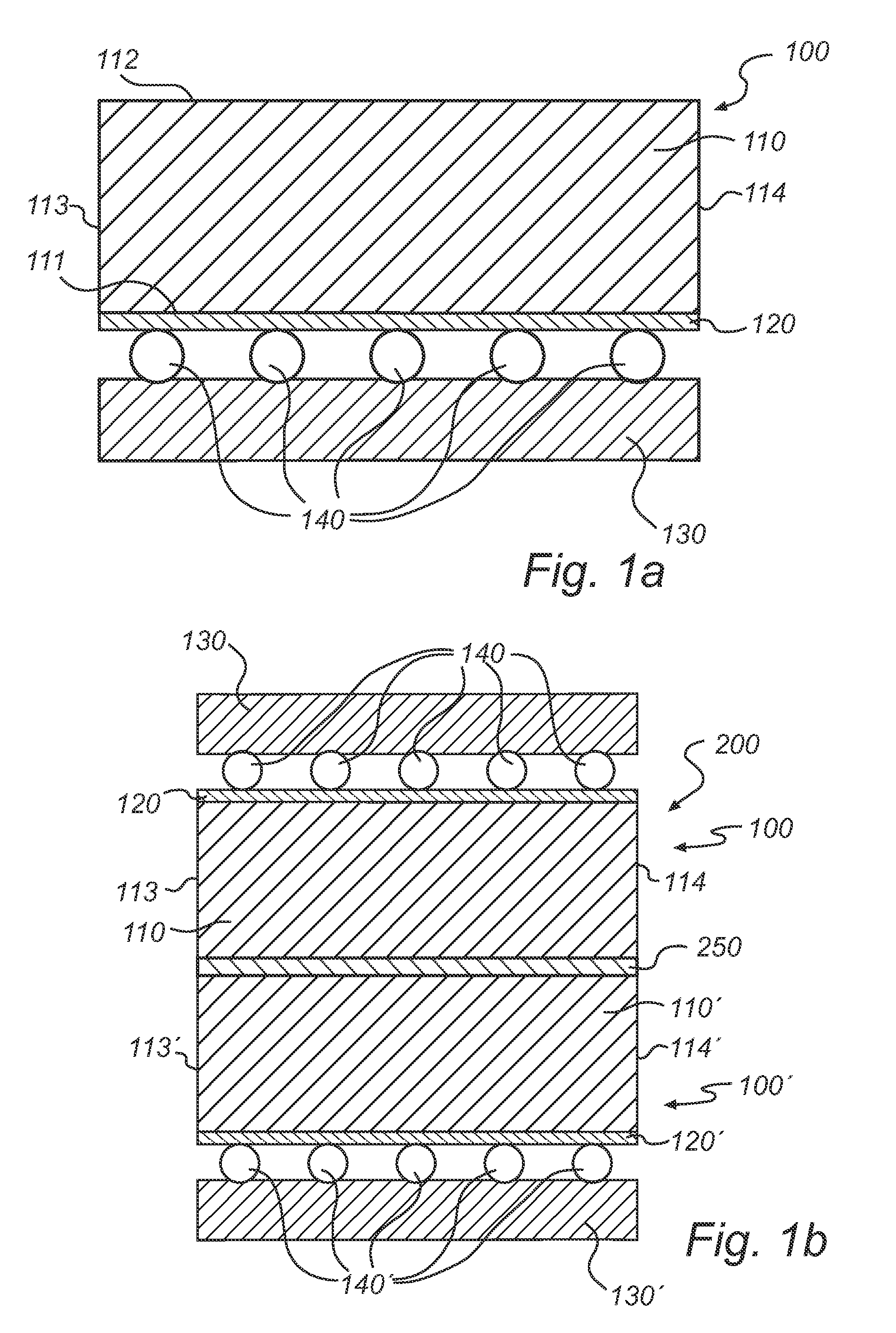
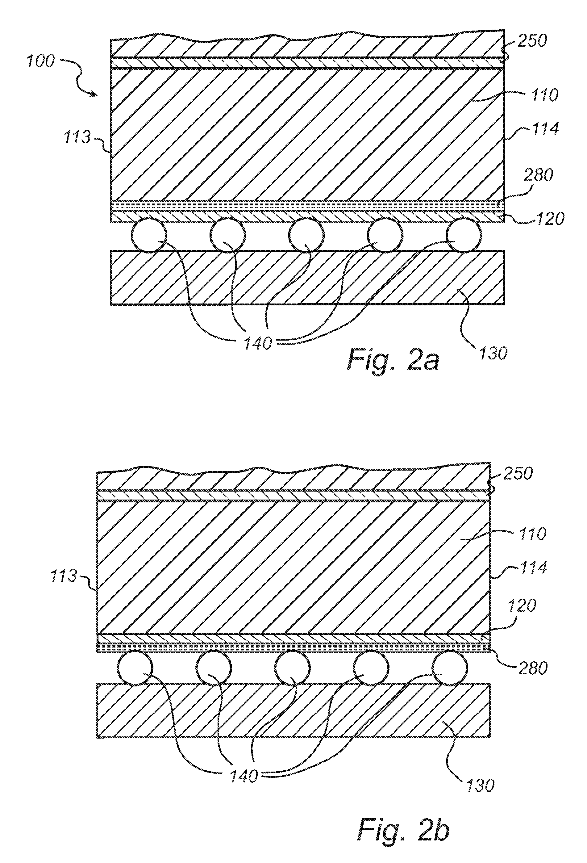
[0041]In a first aspect of the present invention there is provided a side-emitting light device comprising two sub-assemblies which are assembled such that a unitary side-emitting light device is formed. FIG. 1a) illustrates a sub-assembly 100 which comprises a substrate 130 on which one or more light sources 140 are provided. The light sources 140 are optically bonded with a luminescent plate 110. The luminescent plate has a first surface 111 and a second surface 112. The optical bond is arranged such that light produced in the light sources 140 is guided to the luminescent plate 110, in which light is generated by means of photo luminescence, i.e. the light from the light sources is absorbed in and reemitted at longer wavelengths by the luminescent plate material. Thus, the light sources 140 and the material in the luminescent plate 110 must be matched, such that the light sources 140 emit light of a wavelength capable of exciting luminescence light from the luminescent plate 110....


PUM


Abstract

This invention relates to a side-emitting light device comprising two sub-assemblies which are optically bonded together. Each sub-assembly comprises a substrate, at least one light source disposed on the substrate, and a luminescent plate optically bonded with the at least one light source. The light source emits light of a wavelength capable of exciting luminescence light from the luminescent plate. The two sub-assemblies are arranged having the free surface of the luminescent plates facing each other. The side-emitting light device is for instance applicable for light sources comprising naked dies arranged with Thin Film Flip Chip (TFFC) technique or laser diodes.

Description

FIELD OF THE INVENTION[0001]The present invention relates to the field of light devices. More particularly the invention relates to a side-emitting light device and a method for manufacturing such a side-emitting light device.BACKGROUND OF THE INVENTION[0002]State of the art side-emitting light emitting diode devices, LED devices, are commonly used in mobile backlighting applications. The basic structure of a side-emitting LED device in prior art is a substrate with a LED chip and electrical connections, a light guide which is provided with a reflecting structure or top coating which reflects light emitted by the LED chip within the light guide such that the emitted light exits the LED package through a side surface thereof.[0003]US 2006 / 0273337 A1 discloses a side-emitting LED package and a manufacturing method thereof. The side-emitting LED package comprises the basic structure as described above with the light guide constituted by a moulded part having an upper surface with a cen...

Claims


Application Information

Patent Timeline
IPC IPC(8): H01S5/02H01L25/075F21V9/16F21Y101/00
CPCG02B6/005G02B6/0068G02B6/0073G02B6/0076H01L2224/16225G02F1/133621G02F2001/133614G02F2001/133628H01L25/0756G02F1/133615G02F1/133614G02F1/133628
Inventor VAN SPRANG, HENDRIK ADRIANUSDE GRAAF, JAN
Owner KONINKLIJKE PHILIPS ELECTRONICS NV
Why Eureka
Try Eureka