Perforated substrate and a method of manufacture

a manufacturing method and technology of perforated substrate, applied in the manufacture of capacitors, cell components, manufacturing tools, etc., can solve the problems of short circuit, uncontrolled electrical particulars flow, and short circuit between the electrodes of the opposite polarity of the battery, so as to improve the performance and various merits of the battery, improve the manufacturing process efficiency, and high accuracy

Inactive Publication Date: 2017-02-02
LISIT
View PDF12 Cites 3 Cited by
  • Summary
  • Abstract
  • Description
  • Claims
  • Application Information

AI Technical Summary

Benefits of technology

[0010]In the present invention, a steel-printing cylinder is utilized for the manufacture of a thin perforated substrate. This steel-printing cylinder provides for the ease of manufacture and also for the inclusion of a variety of holes inclusions that can control the porosity of the perforated substrate manufactured. The control of the perforated substrate porosity and the pattern included in the perforated substrate is achieved through the implementation of laser imaging and the use of a fluid water based ink on the printing cylinder. The printing cylinder receives a copper electroplating and subsequently a laser marking. The thin film substrate through application of the printing cylinder with the fluid ink is then submitted to an exposure of laser light. The perforated substrate is thus promoted to include the patterned elements of the printing cylinder, with high accuracy and through an efficient manufacturing process.
[0011]The ability to control the printed pattern on the printing cylinder and subsequently the perforated substrate is achieved through the use of laser technology that uses direct laser engraver for embossing cylinder into microns. The particular pattern used for the manufacture of the battery separator is described. This pattern achieves the optimal control mechanism for the flow of charge, and thus improves the performance and various merits of the battery.

Problems solved by technology

Deposits therein develop a formation, which can over time connect through the thickness of the separator membrane and cause an electrical short between the batteries electrodes of opposite polarity.
This will directly effect the tension of the substrate itself, and lead to short circuits and uncontrolled flow of the electrical particulars.
Uneven spatial distribution in the inclusion of elements placed within the perforated substrate leads to an improper flow of electrolyzes within the electrical device, as well as a reduced ability for electrode contact prevention.
Failure in the structural integrity of the separator, such as the inclusion of a high numbers of electrolytes flowing through the battery separator impacts the power generation process within the battery, and makes the battery perform less efficiently.

Method used


Image

  • Perforated substrate and a method of manufacture
  • Perforated substrate and a method of manufacture
  • Perforated substrate and a method of manufacture

Examples


Embodiment Construction

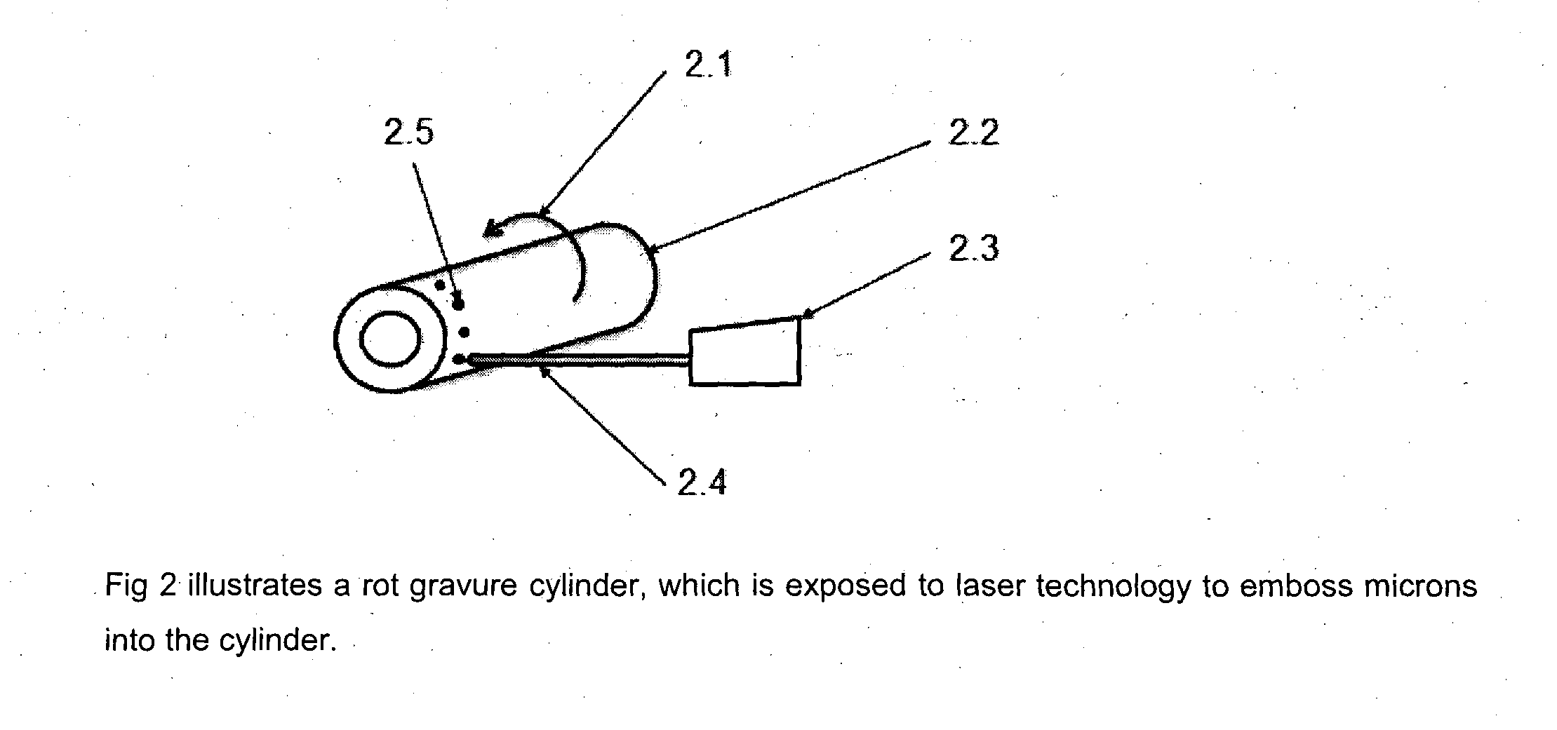
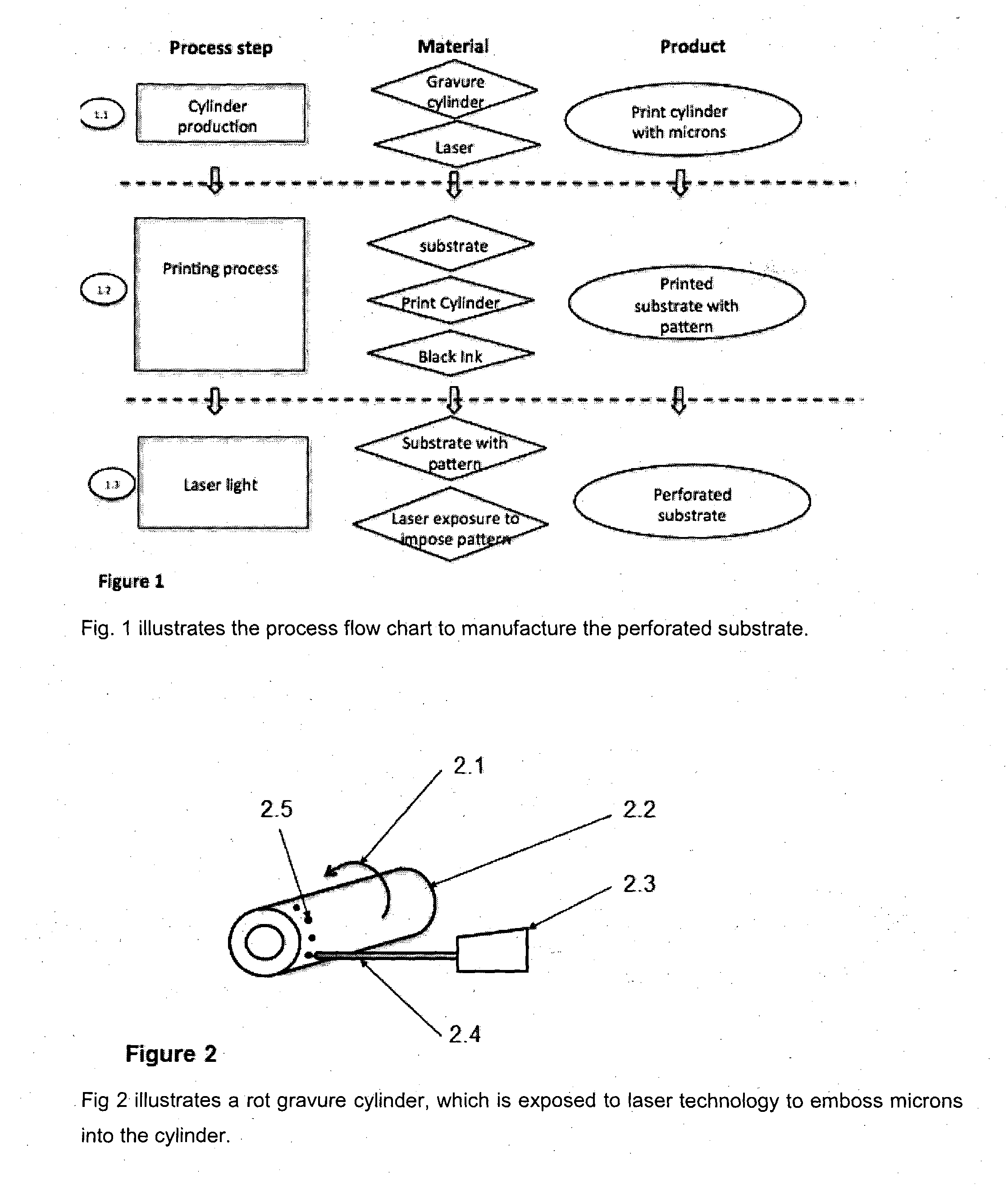
[0038]Description of the Process of Manufacture

[0039]The process of manufacturing a perforated substrate is split in three main steps. The comprising preparation of a printing cylinder, the application of an ink to the substrate with the said printing cylinder, and the subsequently exposing the ink pattern with laser light. The process starts with the process step (1.1) to transform a raw printing cylinder with microns. Therefore a raw standard gravure-printing cylinder which has copper layer applied, as shown in FIG. 2 (2.2). The cylinder (2.2) is manufactured with a hollow body and made of steel. After mechanical completion in steel, the steel roller (2.2) is plated with copper using an electroplating process resulting in an outer copper electroplating. A laser light (2.4) is then applied to the gravure-printing cylinder (2.2), which engraves microns (2.5) onto surface of the cylinder. A chrome layer is applied to protect the outer surface. The result is finished engraved gravure-...


PUM

PropertyMeasurementUnit
heat resistanceaaaaaaaaaa
lengthaaaaaaaaaa
lengthaaaaaaaaaa

Abstract

The present invention relates to an optimization of a perforated substrate and a method of manufacturing the substrate using a printing process. The method of manufacturing the perforated substrate involves a substrate which is printed with ink into black patterns via a printing cylinder. The ink is applied to the substrate with small microns inside the cylinder. The microns are fabricated using laser technology. These black patterns on the substrate are exposed to an infrared light, which creates holes within the substrate. The printed features control the flow of change through the substrate. The substrate can be used in different applications such as filters, membranes of electrical separators. Examples of applications of the material include lithium ion battery separator, capacitors, super capacitors, electrical components, Packaging for the F&B industry in the field of breathable packaging or perishable groceries, filter, micro filter, membranes, energy storage devices, and sailcloth.

Description

BACKGROUND OF THE INVENTION[0001]The present invention relates to a process manufacturing perforated substrate primarily used in electrical devices. The perforated substrate can be used in a wide range of devices including battery separators and capacitors. The electrical separator could be possible used for any kind of electrical separation from anode to cathode. The characteristics also allow the usage in applications such as energy storage, food packaging and sailcloth.[0002]Rechargeable batteries based on the lithium ion technology cell, which moves ions of a source electrode material between the anode and cathode are the primarily use of the perforated substrate. These secondary storage batteries do have a minimum of at least one pair of electrodes of opposite polarity, which are separated with materials such as fleece and ceramic, such as described in patent EP 0618629 A1.[0003]One of the most critical elements of the battery design is the separator component. A good overview ...

Claims


Application Information

Patent Timeline
Patent Type & Authority Applications(United States)
IPC IPC(8): B23K26/382H01M2/16B23K26/18H01M2/18H01M10/0525H01G11/52H01M2/14H01M50/403H01M50/417H01M50/463H01M50/489
CPCB23K26/382H01G11/52H01M2/1653B23K2201/36H01M2/18H01M10/0525B23K26/18H01M2/145Y02E60/13H01G9/02H01G13/00B23K2101/36Y02E60/10H01M50/403H01M50/463H01M50/417H01M50/489
Inventor SIEGLINDE, PRAPANWERNER, JOHANNES MARX-AURNHAMMER
Owner LISIT
Why Eureka
Try Eureka