
Fish Bone Removal Apparatus

Inactive Publication Date: 2017-06-22
CASTEMA INNOVATIONS
View PDF6 Cites 0 Cited by
  • Summary
  • Abstract
  • Description
  • Claims
  • Application Information

AI Technical Summary

Benefits of technology

The present invention aims to improve the process of removing bones, particularly pin bones, from fish bodies, especially white fish bodies. The technical effects of the invention are to provide an apparatus and method for better bone removal that overcomes previous problems and achieves a higher efficiency in the process.

Problems solved by technology

The preparation of fish fillet is a time consuming and cumbersome process.
Especially, removing bones from the meat can be problematic, because these bones are attached to the meat.
Although known apparatus can be used for removal of bones and pin bones from a fish body, these apparatus are not efficient for use in removal of all pin bones, especially not breakable pin bones, such as pin bones from white fish.
A problem with this apparatus is that it is difficult for the fish bones to get caught by the wedge shaped gap.
Another problem with this apparatus is that it is difficult to remove the fish bones from the apparatus when it has been caught by the apparatus.
The removal of fish bones causes stop in the production and accordingly loss of money.
Another disadvantage with the prior art fish bone removal apparatus is that the peripheries of the discs may cause damages on the fish files, thereby causing wastage of the fish meat.

Method used


Image

  • Fish Bone Removal Apparatus
  • Fish Bone Removal Apparatus
  • Fish Bone Removal Apparatus

Examples


Embodiment Construction

[0049]A fish bone removal apparatus of the present invention can be used to remove bones and pin bones from fish. Any type of fish can be used in the fish bone removal apparatus. Examples of fish may be salmon, pollack, haddock, mockery, scrod, whitefish, and the like. The fish bone removal apparatus is especially suitable for removal of pin bones, which easily break during removal of the bone from the meat of the fish, such as pin bones from white fishes.

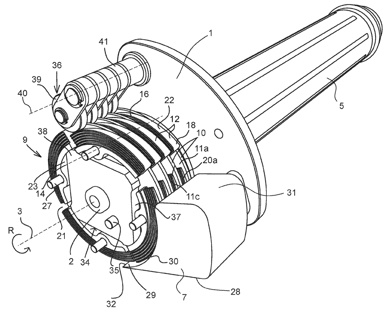
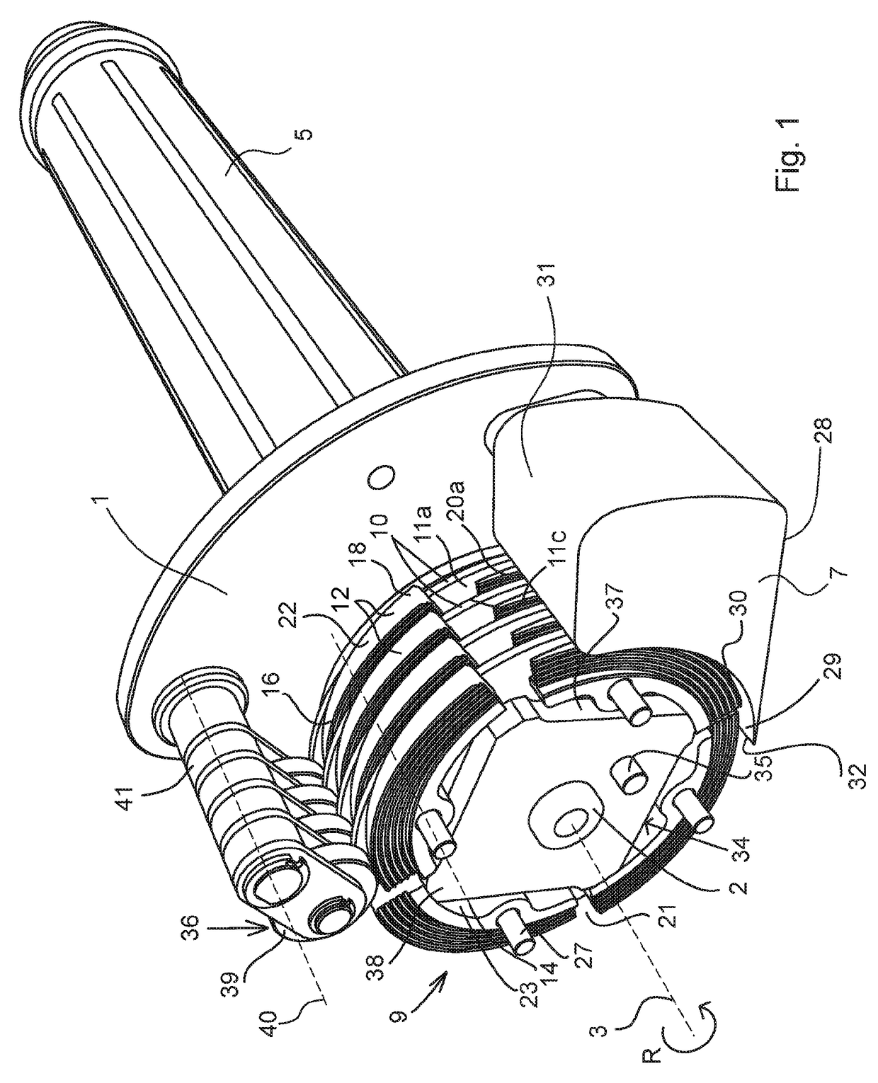
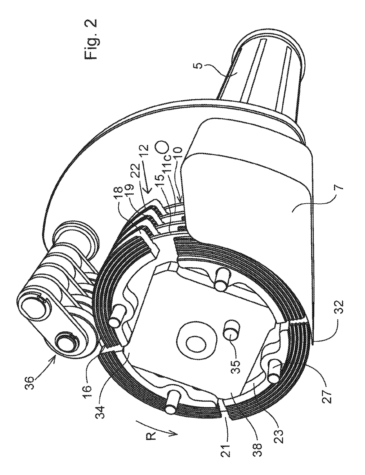
[0050]FIG. 1 shows a perspective view of a fish bone removal apparatus according to an embodiment of the present invention seen from above. FIG. 2 shows a perspective view of the fish bone removal apparatus in FIG. 1 seen from below. FIG. 3 shows a side view of the fish bone removal apparatus. FIG. 4 shows a rear view of the fish bone removal apparatus. FIG. 5 shows an exploded view of the fish bone removal apparatus.

[0051]The fish bone removal apparatus comprises a frame 1, and a rotatable shaft 2 that extends along a first rotati...


PUM


Abstract

The present invention relates to a fish bone removal apparatus comprising a frame (1), a picking member (9) rotatably mounted in relation to the frame about a rotational axis (3), and an actuator arranged to rotate the picking member in a rotational direction. The picking member comprises a first and a second rotating element (10, 12) arranged to form a wedge-shaped gap (24) between them for receiving a bone. The wedge-shaped gap is tapered in a direction opposite the rotational direction of the picking member. The first rotating element is disc shaped and has two parallel radial surfaces and an outer circumferential surface (11c). The second rotating element (12) comprises a bent elongated body having a periphery with a bending radius corresponding to the bending radius of a periphery of the first rotating element, two radial surfaces and an outer circumferential surface (22). The radial surfaces of the first rotating element are arranged in parallel with a plane perpendicular to the first rotational axis, and the radial surfaces of the second rotating element are arranged angled to said plane, so that the outer circumferential surface (22) of the second rotating element is tapered in the rotational direction of the picking member. The first and second rotating element are disposed so that one of the radial surfaces of the first rotating element faces one of the radial surfaces of the second rotating element, and so that the periphery of the first rotating element and the periphery of the second rotating element are positioned on the same distance from the first rotational axis.

Description

FIELD OF THE INVENTION[0001]The present invention relates to a fish bone removal apparatus for removal of bones from a fish body. The present invention particularly relates to a fish bone removal apparatus for removal of pin bones from a fish body.BACKGROUND OF THE INVENTION AND PRIOR ART[0002]The preparation of fish fillet is a time consuming and cumbersome process. Especially, removing bones from the meat can be problematic, because these bones are attached to the meat. Some fishes, such as white fishes have rather thin bones that break easily during the preparation process. This is especially true for pin bones extending from the bigger bones that run along the length of the fish.[0003]Different apparatus have been developed for the removal of bones from meat. Usually, a fish is cleaned such that a fish body is obtained comprising half the side of a fish with bones still attached to the meat. This fish body is then processed in a fish bone removal apparatus.[0004]Although known a...

Claims


Application Information

Patent Timeline
IPC IPC(8): A22C25/16
CPCA22C25/166
Inventor KOLJONEN, KARI
Owner CASTEMA INNOVATIONS
Learn More