Swirling type micro-bubble generating system

a micro-bubble generating system and swirling technology, applied in the direction of carburetor air, combustion-air/fuel-air treatment, separation process, etc., can solve the problems of increasing power consumption, difficult to generate air bubbles of smaller diameter, and clogging of pores

Inactive Publication Date: 2007-11-22
OHNARI HIROFUMI
View PDF16 Cites 6 Cited by
  • Summary
  • Abstract
  • Description
  • Claims
  • Application Information

AI Technical Summary

Benefits of technology

[0022] a third step of continuously and steadily cutting off and smashing said swirling gas cavity in said cylindrical space, whereby the fluid passing through the rotating cut-off portion is rapidly expanded in conical shape while rotating (where a fluid not containing micro-bubbles flowing from outside is filled in the rotating fluid expanding in conical shape), said rotating fluid expanding in conical shape being stably formed, and expanded angle of the conical shape is large (about 90°), and the difference of rotating velocity in the rotating cut-off portion and the smashed portion in the second step is relatively increased.

Problems solved by technology

Thus, it is difficult to generate air bubbles of smaller diameter.
Also, there are problems such as clogging of the pores or increase of power consumption caused by the operation for long time.
Also, there are problems of power consumption increase and the problem of corrosion of vanes or vibration caused by generation of cavitation.
Further, there are problems in that only a small amount of micro-bubbles can be generated.
In the system where gas-liquid two-phase flow collides with the moving vane or projection, fishes or small aquatic animals in natural lakes or culture tanks may be injured, and this causes trouble in the development and maintenance of the environmental condition necessary for the growth of fishes and other aquatic animals.
Further, in the pressurizing system, the system must be designed in larger size and requires higher cost, and operation cost is also high.

Method used


Image

  • Swirling type micro-bubble generating system
  • Swirling type micro-bubble generating system
  • Swirling type micro-bubble generating system

Examples


Embodiment Construction

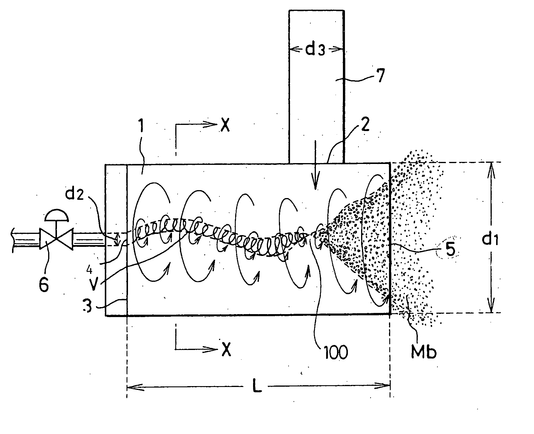
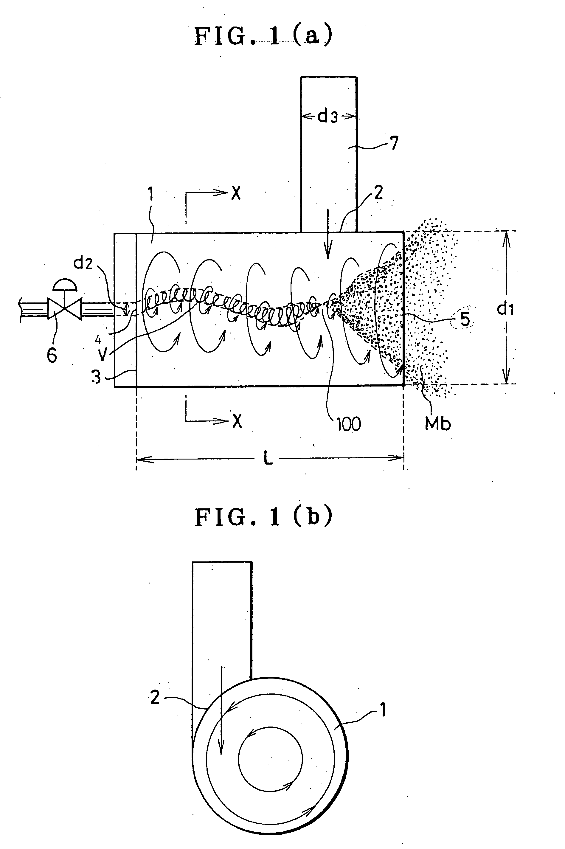
[0050] As shown in the drawing to explain the principle of the present invention in FIG. 1, a micro-bubble generating system comprises a cylindrical space with bottom 1 formed in a container of the system, a pressure liquid inlet 2 provided in tangential direction on a part of circumferential surface of inner wall of the space, a gas introducing hole 4 arranged at the center of a bottom 3 of the cylindrical space, and a swirling gas-liquid mixture outlet 5 arranged near the top of the cylindrical space 1.

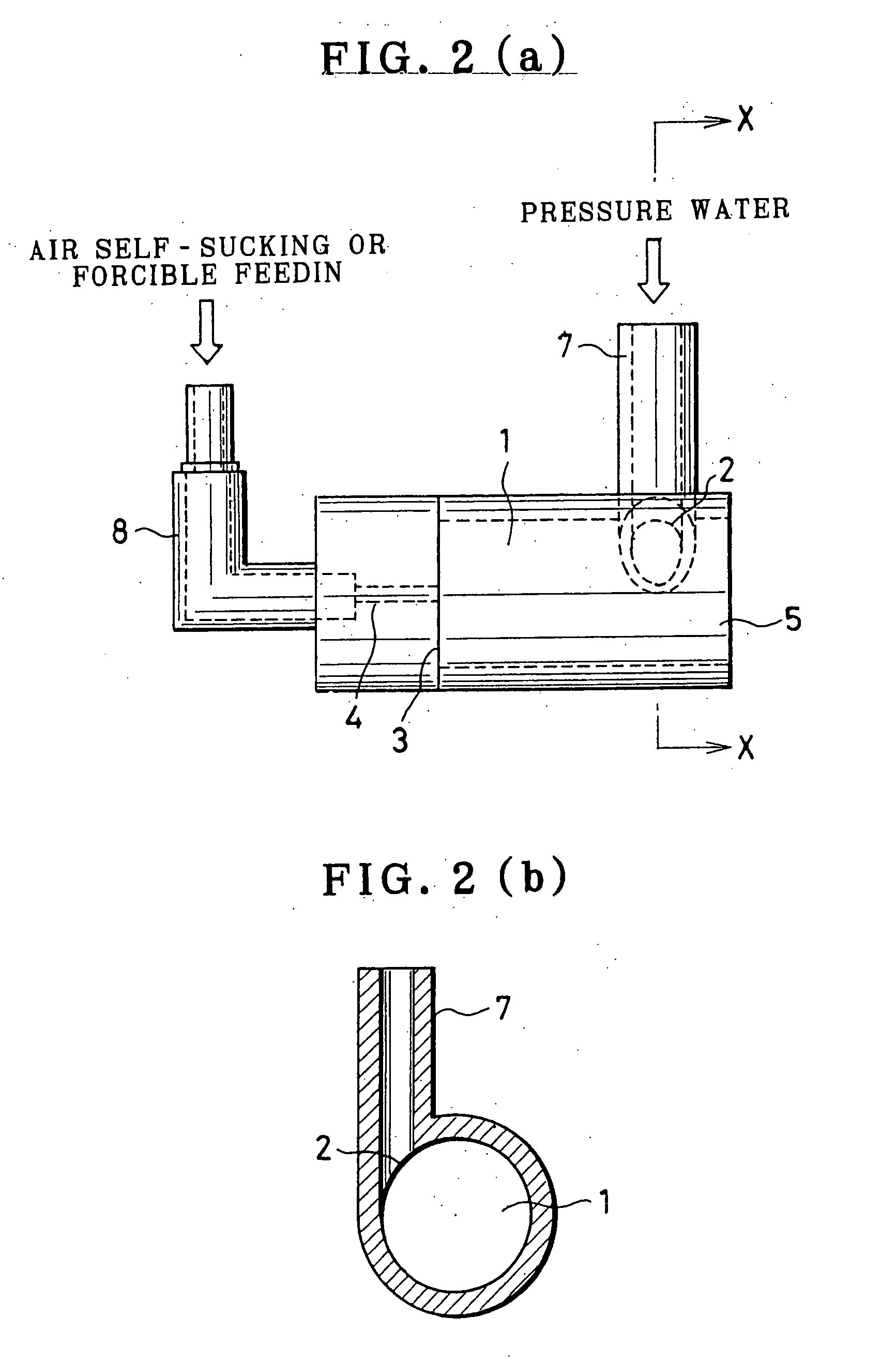
[0051]FIG. 1 (a) is a side view, and FIG. 2 (b) is a sectional view along the line X-X of FIG. 1 (a).

[0052] The main unit of the system or at least the swirling gas-liquid mixture outlet 5 is installed in the liquid. By forcibly sending the pressure liquid into the cylindrical space 1 through the pressure liquid introducing hole 2, a swirling flow is generated in the space, and a portion with negative pressure is generated near the axis of the cylindrical pipe.

[0053] By this-nega...


PUM

PropertyMeasurementUnit
diameteraaaaaaaaaa
diameteraaaaaaaaaa
thicknessaaaaaaaaaa

Abstract

The swirling type micro-bubble generating system according to the present invention comprises a container main unit having a cylindrical space with bottom or a megaphone-like space, a liquid inlet provided in tangential direction on a part of circumferential surface of inner wall of said space, a gas introducing hole provided on the bottom of said cylindrical space or opening of said megaphone-like space, and a swirling gas-liquid mixture outlet arranged at the top of said cylindrical space or opening of said megaphone-like space. According to this system, it is possible to readily generate micro-bubbles in industrial scale, and the system is relatively small in size and has simple structure and can be easily manufactured. The system can be used in the applications such as purification of water quality in ponds, lakes, marshes, man-made lakes, rivers, etc., for processing of polluted water using microorganisms, culture of fishes and other aquatic animals, and increase of oxygen and dissolved oxygen in culture solution in hydroponics culture farm and improvement of production yield.

Description

FIELD OF THE INVENTION [0001] The present invention relates to a micro-bubble generating system for efficiently dissolving gas such as the air, oxygen gas, etc. into liquid such as city water, river water, etc., for purifying polluted water and for effectively utilizing the water for reconditioning and renewal of water environment. BACKGROUND ART [0002] In conventional type aeration systems, e.g. in most of aeration systems using micro-bubble generating system installed for culture and growth of aquatic animals, air bubbles are generated by injecting the air under pressure into water through fine pores of tubular or planar micro-bubble generating system installed in the tank, or air bubbles are generated by introducing the air into water flow with shearing force or by vaporizing the air dissolved in water by rapidly reducing pressure of the pressurized water. [0003] In the aeration process using the micro-bubble generating system with the above functions, operation is basically cont...

Claims


Application Information

Patent Timeline
Patent Type & Authority Applications(United States)
IPC IPC(8): B05B7/10B01F3/04B01F5/00B01F5/06C02F7/00
CPCB01F3/0446B01F5/0057B01F5/0663Y10S261/75B01F2003/04858C02F7/00B01F5/0679Y02W10/10B01F23/232B01F23/2373B01F25/10B01F25/4412B01F25/4421B01F23/2326
Inventor OHNARI, HIROFUMI
Owner OHNARI HIROFUMI
Why Eureka
Try Eureka