Continuous dehydration of alcohol to ether and water used as fuel for diesel engines

a technology of diesel engine and alcohol, which is applied in the direction of domestic stoves or ranges, heating types, applications, etc., can solve the problems that the majority of the energy contained in the exhaust gas is normally wasted as heat loss, and achieves the effects of reducing emissions, ensuring energy supply, and increasing overall fuel efficiency

Inactive Publication Date: 2008-11-11
HALDOR TOPSOE AS
View PDF13 Cites 68 Cited by
  • Summary
  • Abstract
  • Description
  • Claims
  • Application Information

AI Technical Summary

Benefits of technology

[0019]The present invention relates to a more sustainable energy supply situation for the transportation sector for the coming decades if used as the invention suggests. Higher overall fuel efficiency is obtained. At the same time, reduced emissions of environmentally harmful components such as particulate matter (PM) and oxides of nitrogen (NOx) are achieved. Also a reduction in carbondioxide (CO2) is obtained. As a consequence of the technological achievements written in the present invention, a ramification of the possible sources for fuel manufacturing are enabled; not only neat methanol produced from natural gas, also methanol produce from coal or renewable like wood can be used. Even use of garbage could be possible. Higher alcohol especially ethanol can be produced from renewable sources and used in blends with methanol. Mixtures containing methanol / ethanol and water are suitable within a specified written limited area. The alcohol mixtures are converted on board a vehicle to the associated ether and water. The obtained fuel compositions are suitable for use in compression ignition internal combustion engines equipped with inlet air heater. Use of diesel in diesel engines is associated with a surplus of heat released during combustion. Exhaust gas temperatures from 200° C. to more than 500° C. are typical depending on the engine load. Most of this energy contained in the exhaust gas is normally wasted as heat loss. In the present invention this energy is used for the evaporation and heating of the alcohol fuel used. Further, the surplus heat is used to preheat the air used for the combustion.
[0020]The synergetic combination of fuel and heat management results in the achieved high fuel efficiency and the low concentrations of harmful spices in the tail gas.

Problems solved by technology

Most of this energy contained in the exhaust gas is normally wasted as heat loss.

Method used


Image

  • Continuous dehydration of alcohol to ether and water used as fuel for diesel engines
  • Continuous dehydration of alcohol to ether and water used as fuel for diesel engines
  • Continuous dehydration of alcohol to ether and water used as fuel for diesel engines

Examples


example 1

Neat DME as Reference Fuel (Fuel No. 1)

[0046]The engine was started on neat DME. The engine load was adjusted to 1 kW and stabilised. The engine was operated for approximately 5 minutes—until stable exhaust temperature was seen. All measurable parameters as described were measured and noted every minute on a log sheet. Then the inlet temperature of the intake air was heated to 125° C. After stabilisation a new set of measurements was executed. Inlet air heating was cut-off and the engine was stopped.

[0047]The results of these two data sets are shown in Table 3. All measured components (NOx, HC, CO, O2, CO2) in the exhaust gas are given as volume amounts. Fuel consumption (FC) are given as actual consumption in g / hour and as calculated values as MJ / hour based on energy content specified as lower heating value (LHV) of the specific fuel tested given in Table 1.

[0048]

TABLE 3Inlet AirExhausttemper-temper-atureatureFCFCNOxHCCOO2CO2° C.° C.gram / hMJ / hPPMPPM%%% 1020678822.741191630.07316.13...

example 2

Diesel as Reference Fuel (Fuel No. 2)

[0050]In order to compare fuel consumption and emissions diesel fuel was applied as fuel. The Swedish low sulphur fuel type MK-1 was selected for this purpose. The engine was operated without preheated air only. The results are given in Table 4.

[0051]

TABLE 4Inlet AirExhausttemper-temper-atureatureFCFCNOxHCCOO2CO2° C.° C.gram / hMJ / hPPMPPM%%%10204538.822.63388310.06315.73.8

Discussion of Results

[0052]It appears that the efficiency is almost the same as obtained with neat DME fuel. Emissions of NOx were more than 3 times higher with diesel fuel compared to the DME operation.

example 3

Diesel Fuel Composition (Fuel No. 3)

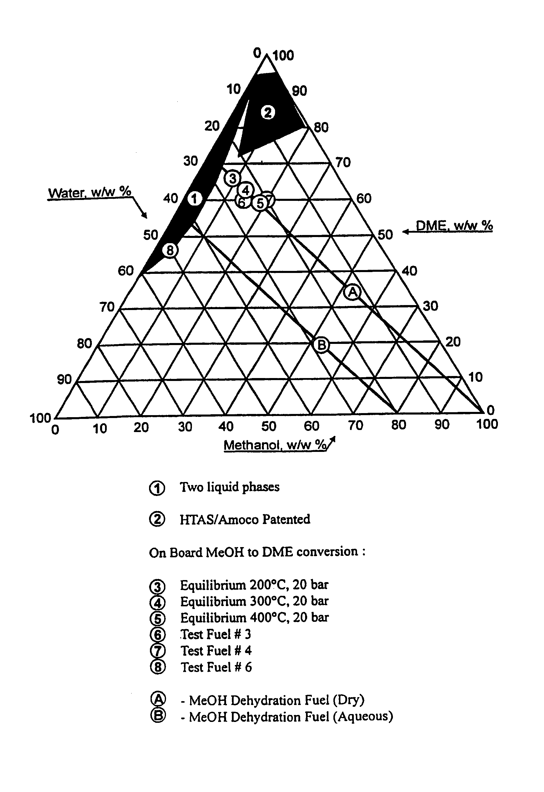
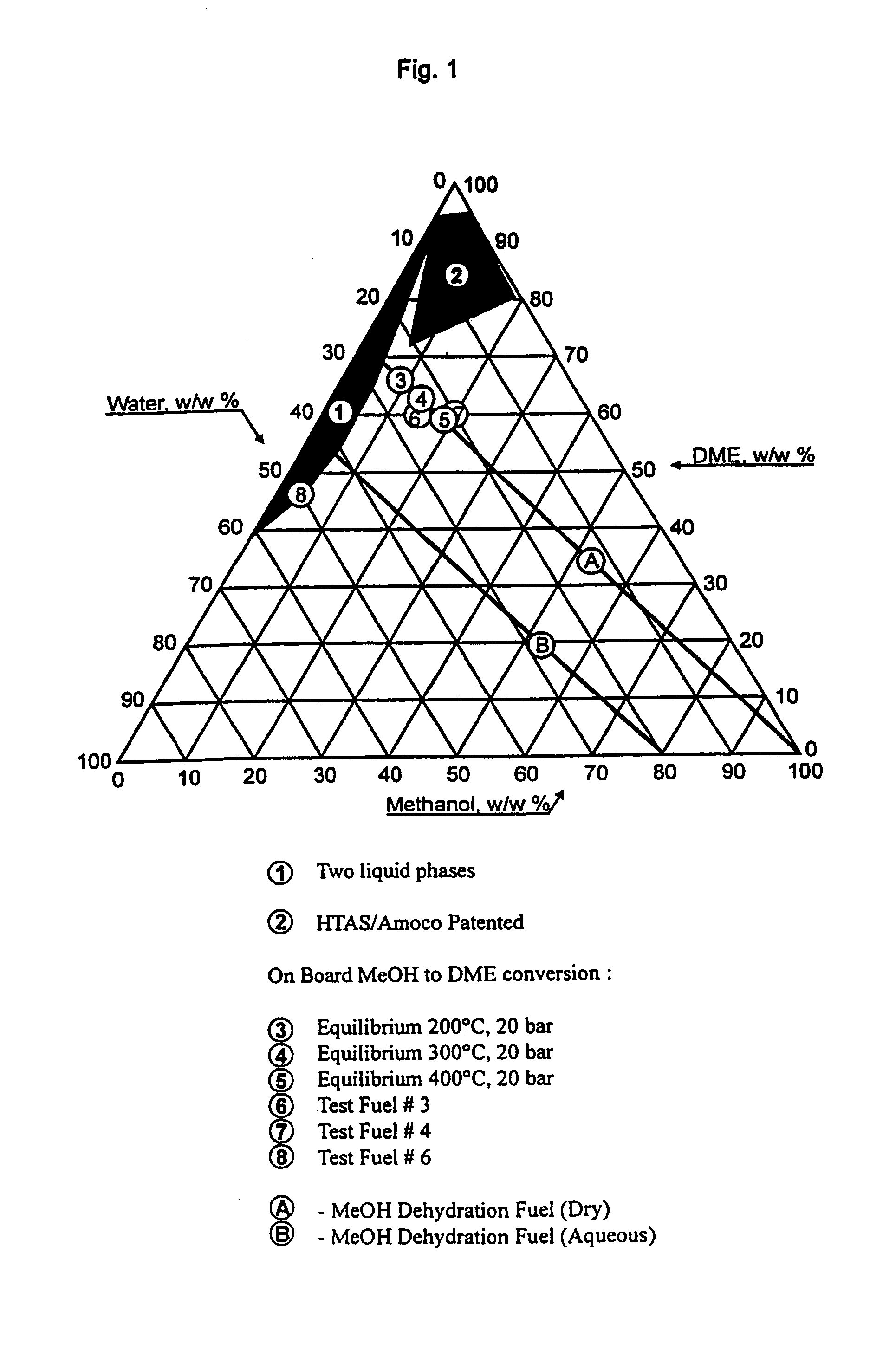
[0053]DME / methanol / water composition=60 / 15 / 25 wt / wt %.

[0054]According to the chemical equilibrium calculations shown in FIG. 1 concentrations close to 60% DME, 15% methanol and 25% water all by mass are obtained at 300° C. dehydration temperature and 20 bar. A fuel mixture having this composition was prepared and tested according to the test procedure described above. The diesel engine was started on neat DME. Load on the engine was set to 40% by means of the electrical heater (1 Kw). Air inlet was heated to 124° C. and stabilised. The 3-way valve was switched from neat DME to fuel No. 3. It was observed that the engine kept running on the specified fuel composition. The fuel consumption and emissions were measured. The air inlet temperature were reduced to 105° C. The engine operation was slightly uneven. Fuel consumption was calculated and emissions measured. Further reduction of air inlet temperature to 80° C. resulted in a definitely more unev...


PUM

PropertyMeasurementUnit
pressureaaaaaaaaaa
pressureaaaaaaaaaa
temperatureaaaaaaaaaa

Abstract

The present invention relates to an oxygenated fuel composition suitable for use in compression ignition internal combustion engines, equipped with inlet air heater and catalytic alcohol dehydration equipment suitable for chemical equilibrium conversion of methanol and higher alcohol to their associated ether plus water.

Description

FIELD OF INVENTION[0001]This invention relates to improved fuels for compression ignition internal combustion engines equipped with inlet air heater. More particular, this invention relates to oxygenated diesel fuel compositions, which contain a combination of alcohol, ether and water. The ratio of alcohol / ether / water is selected by catalytic dehydration of alcohol. The fuel compositions are obtained by means of a catalytic dehydration unit by which a catalytic dehydration unit by which heat is provided by the engine exhaust provides heat by the engine exhaust. The obtained advantages are low emissions and high engine efficiency.BACKGROUND OF THE INVENTION[0002]Since Rudolf Diesel invented the basic diesel engine concept in 1893 constant improvements have been reached. The engine efficiency has increased from 5 to more than 40% today. Through decades of continues development work and efforts, reliability, drive ability and performance of this engine type have resulted in global acce...

Claims


Application Information

Patent Timeline
Patent Type & Authority Patents(United States)
IPC IPC(8): C10L1/18F01N5/02C10L1/00C10L1/02F02B3/06F02B51/02F02M21/08F02M25/00F02M27/02F02M31/08F02M37/00
CPCC10L1/026F02B3/06Y02E50/13Y02E50/10
Inventor MIKKELSEN, SVEND-ERIKLEHRMANN, PETERHANSEN, JOHN BOGILD
Owner HALDOR TOPSOE AS
Why Eureka
Try Eureka