Eureka AIR delivers breakthrough ideas for toughest innovation challenges, trusted by R&D personnel around the world.

Production of electrolytic water

a technology of electrolysis water and production line, which is applied in the direction of water/sewage treatment by electrochemical methods, separation processes, disinfection, etc., can solve the problems of poor electrolysis efficiency, strong odor, corrosion, etc., and achieve the effect of preventing adhesion of scale and increasing free chlorine production efficiency

Inactive Publication Date: 2005-09-01
ELECTROLYZER
View PDF3 Cites 67 Cited by
  • Summary
  • Abstract
  • Description
  • Claims
  • Application Information

AI Technical Summary

Benefits of technology

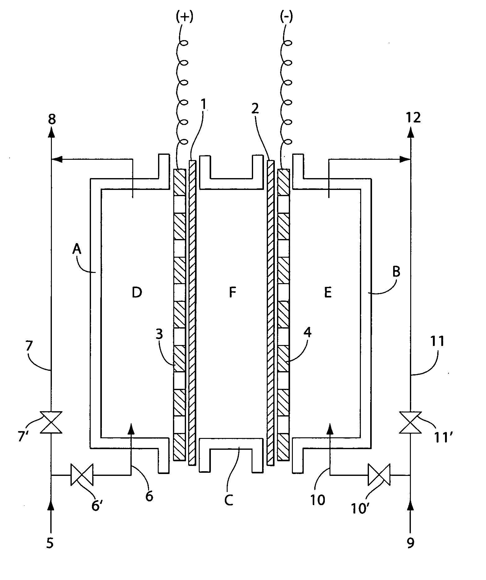
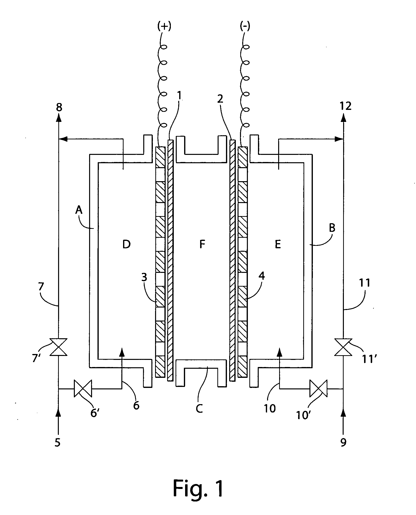
[0008] A method is described for production of electrolytic water, employing the system of first dividing the feed water supplied to the anode into water for electrolysis and water not for electrolysis, conducting the water for electrolysis through the anode chamber to be electrolyzed, mixing the electrolytic water discharged from the anode chamber with the water not for electrolysis, and second, dividing the feed water supplied to the cathode into water for electrolysis and water not for electrolysis, conducting the water for electrolysis through the cathode chamber to be electrolyzed, and mixing the electrolytic water discharged from the cathode chamber with the water not for electrolysis. Electrolysis is conducted by charging the anode plate and the cathode plate with at least 1500 coulombs of direct current per liter of electrolytic water actually electrolyzed. This method can increase free chlorine production efficiency and prevent adhesion of scale to the electrodes.
[0009] Also described herein is a method of producing electrolytic water using an electrolyzer provided with an anode chamber, a cathode chamber, and an intermediate chamber between the anode chamber and the cathode chamber separated from the latter two chambers by two membranes. Contact between negative electrolyte ions (e.g., chloride ions) and the anode plate is increased by increasing the number of anode plates placed in the anode chamber. This raises the reaction efficiency of the anode and increases production of chlorine gas, as well as hypochlorous acid, which is the reaction product of water with chlorine gas. This method can produce acidic electrolytic water of about pH 3 to about pH 5 with at least 15 ppm free chlorine content and no more than 100 ppm chloride ion concentration. This electrolytic water has the properties of a long-lasting bactericidal effect and decreased corrosion of metals.

Problems solved by technology

In addition, strong odor is a problem when used to disinfect the oral cavity such as in dentistry or as a mouthwash.
Corrosion can also be a problem depending on the type of metals used when disinfecting or washing.
Thus, there are many application-specific demands on acidic electrolytic water and alkaline electrolytic water.
In addition to application-specific requirements, previous methods for producing acidic electrolytic water and alkaline electrolytic water by electrolyzing water also have many general problems, such as (1) poor electrolysis efficiency and high power consumption, (2) difficulty in controlling the free chlorine content in acidic electrolytic water, (3) corrosion and salt damage caused by a high electrolyte (i.e., salt) content in acidic electrolytic water, and (4) scale adhering to the electrodes due to electrolysis, resulting in decreasing efficiency as the scale builds up.
Although acidic electrolytic water produced by previous methods is in great demand in fields seeking to take advantage of its superior bactericidal effect, the greatest drawbacks of this water are the short duration of its bactericidal effect and its high corrosiveness to metals such as medical instruments.
Produced in this way, the bactericidal effect of acidic electrolytic water is of short duration (usually one week or less) and it tends to corrode metals.
Eventually, the degree of deformation exceeds the permissible range due to prolonged repetition of this deformation, and the membranes break.
In addition, if the amount and electrolyte concentration of the solution within the electrolysis chambers fluctuates greatly, for example, from fluctuations in feed water pressure, electrolysis may fail.
As a result, it becomes difficult to produce electrolytic water in a reliable and well-controlled manner and improvements are needed to ameliorate these general difficulties, as well as to provide a greater ability to modify the characteristics of the electrolytic water in order to better meet application-specific requirements.

Method used


Image

  • Production of electrolytic water
  • Production of electrolytic water
  • Production of electrolytic water

Examples


example 1

[0072] This example describes using the water electrolyzer shown in FIG. 3. The size of the electrolytic bath was 5 cm long, 9 cm wide, and 6 cm thick. An electrode having platinum / lithium oxide baked onto a titanium plate with an effective surface area of 50 cm2 and having many holes in it was used as the anode plate (3), and an electrode having platinum plated on a titanium plate with an effective surface area of 50 cm2 and having holes in it was used as the cathode plate (4). The nonconductive material of a fluorinated resin (Teflon®) sheet with holes was laminated on the side of each electrode plate facing the membrane. An MF film of unwoven fabric was used for membrane (1) separating the anode chamber from the intermediate chamber, and a cation exchange resin film was used for membrane (2) separating the cathode chamber from the intermediate chamber.

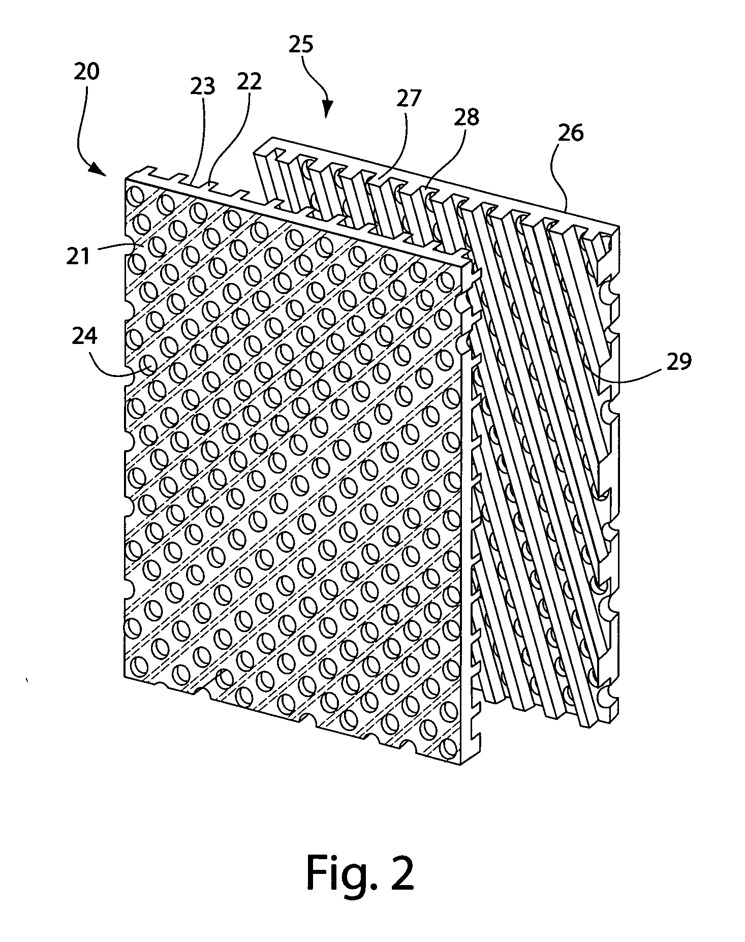
[0073] The rigid plates shown in FIG. 2 were used on these membranes (1) and (2), and were made of synthetic resin. The size of t...

example 2

[0077] The same operations as Example 1 were performed using the same electrolyzer except for using an anode of platinum plated on a titanium plate instead of platinum / lithium oxide baked onto a titanium plate. Investigating the production efficiency of effective chlorine in this case gave the results shown in Table 2. From Table 2, it can be confirmed that a high content of chlorine was produced.

TABLE 2PowerWater forWater Not forVoltageCurrentConsumptionElectrolysisElectrolysisORPFree ChlorineVAWL / minL / minpHmVppm5.88.951.6 0.031.52.8611381306.28.955.20.11.52.7411411106.48.957.00.21.52.721142105

example 3

[0078] This example describes the water electrolyzer shown in FIG. 5. An electrode having platinum / lithium oxide baked onto a titanium plate with an effective surface area of 50 cm2 and holes (diameter: 1.0 to 3.0 mm) was used as the anode electrode plate (3). Two, three, and five plates were used as anode electrode plates, and measurements were taken for each combination. When several electrodes were used, part of each of the electrode plates are in electrical contact. An electrode having platinum plated on a titanium plate with an effective surface area of 50 cm2 (square centimeters) and holes (diameter: 1.0 to 3.0 mm) was used as cathode plate (4). A cation exchange resin film was used for membrane (1) separating the anode chamber from the intermediate chamber, and an anion exchange resin film was used for membrane (2) separating the cathode chamber from the intermediate chamber. Intermediate chamber (F) was filled with an approximately 30% concentration aqueous sodium chloride s...


PUM

PropertyMeasurementUnit
Electric chargeaaaaaaaaaa

Abstract

Apparatus and methods are provided for producing electrolytic water using three chambers, rigid plates and ion exchange membranes. Benefits include reduced scale production and increased long-term bactericidal effects of the water produced.

Description

FIELD OF THE INVENTION [0001] The invention pertains to the production of acidic electrolytic water and alkaline electrolytic water by electrolyzing water. BACKGROUND [0002] Acidic electrolytic water and alkaline electrolytic water have been produced by electrolyzing water that has a small amount of an electrolyte added. Acidic electrolytic water produced by this method has a hydrogen ion concentration (pH) in a range of 2.0 to 3.5 (generally 2.2 to 3.0), shows at least 1100 mV oxidation reduction potential (ORP), and contains at least 10 ppm free chlorine (also known as effective chlorine; primarily hypochlorous acid below pH 7). Because this type of acidic electrolytic water contains free chlorine, it is strongly acidic and has a high oxidation reduction potential, it has a potent bactericidal effect on E. coli and other bacteria, and has begun to be widely used in recent years in fields such as medicine, agriculture, and dairy farming. Because it has a pH in a range of 10.5 to 12...

Claims


Application Information

Patent Timeline
IPC IPC(8): C02F1/00C02F1/46C02F1/461C25D17/00
CPCC02F1/4602C02F1/4618C02F2001/46119C02F2301/043C02F2001/46185C02F2001/4619C02F2201/46115C02F2001/46133
Inventor SANO, YOICHI
Owner ELECTROLYZER
Why Eureka
Eureka Blog
Learn More