
Display device and method of driving the display device

a display device and display technology, applied in the field of display devices, can solve the problems of increasing the overall power consumption of the liquid crystal display employing ccfl, light loss, and difficulty in applying ccfl to a large-sized liquid crystal display over 30 inches, and achieve the effect of improving dynamic contrast and improving display quality

Inactive Publication Date: 2007-11-22
SAMSUNG SDI CO LTD
View PDF9 Cites 37 Cited by
  • Summary
  • Abstract
  • Description
  • Claims
  • Application Information

AI Technical Summary

Benefits of technology

[0015]Exemplary embodiments in accordance with the present invention provide a display device that can realize an improved display quality by improving the dynamic contrast and a method of driving the display.
[0016]Exemplary embodiments in accordance with the present invention provide a display device that can reduce power consumption and minimize a light loss that may be caused by an optical member and a method of driving the display.

Problems solved by technology

However, since the CCFL emits the light through the optical member, there may be a light loss.
Furthermore, since the CCFL has relatively higher power consumption, the overall power consumption of the liquid crystal display employing the CCFL increases.
In addition, since the CCFL is difficult to be large-sized due to its structural limitation, it is hard to apply CCFL to a large-sized liquid crystal display over 30-inch.
However, the LED is costly and increases an overall thickness of the liquid crystal display.
Therefore, it is difficult to improve the display quality to a sufficient level.

Method used


Image

  • Display device and method of driving the display device
  • Display device and method of driving the display device
  • Display device and method of driving the display device

Examples


Embodiment Construction

[0036]The present invention will now be described more fully with reference to the accompanying drawings, in which exemplary embodiments of the invention are shown. The invention may, however, be embodied in many different forms and should not be construed as being limited to the embodiments set forth herein; rather these embodiments are provided so that this disclosure will be thorough and complete, and will fully convey the concept of the invention to those skilled in the art.

[0037]In the following description, a liquid crystal display will be illustrated as an example of a display device of an embodiment of the present invention. However, the present invention is not limited to this example. That is, the concept of the present invention can be applied to a non-self-emissive display device, which displays an image by receiving light from a backlight unit using a light receiving element.

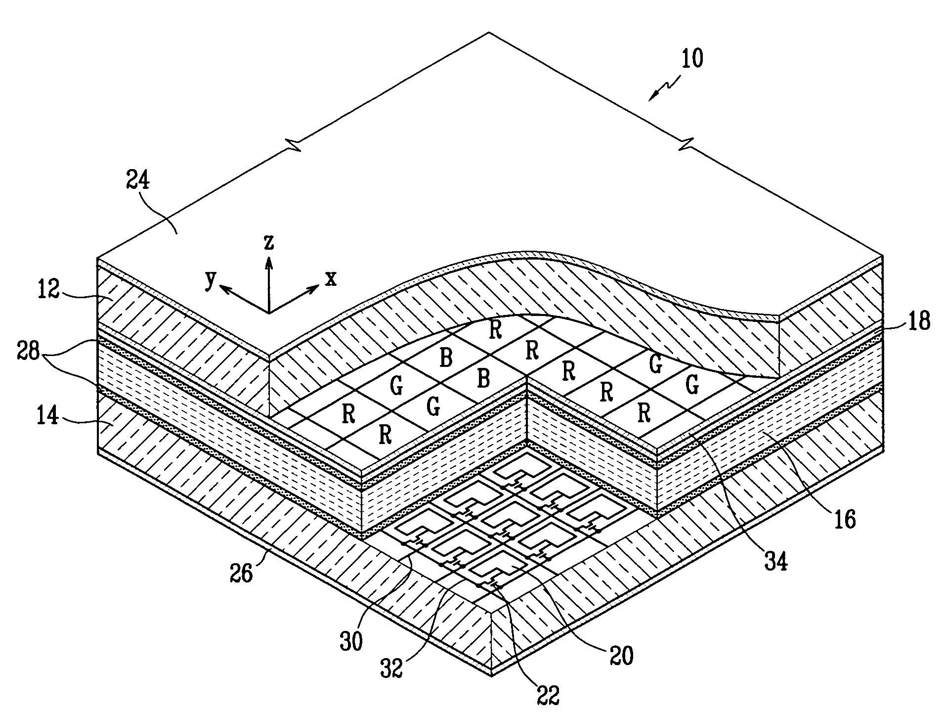
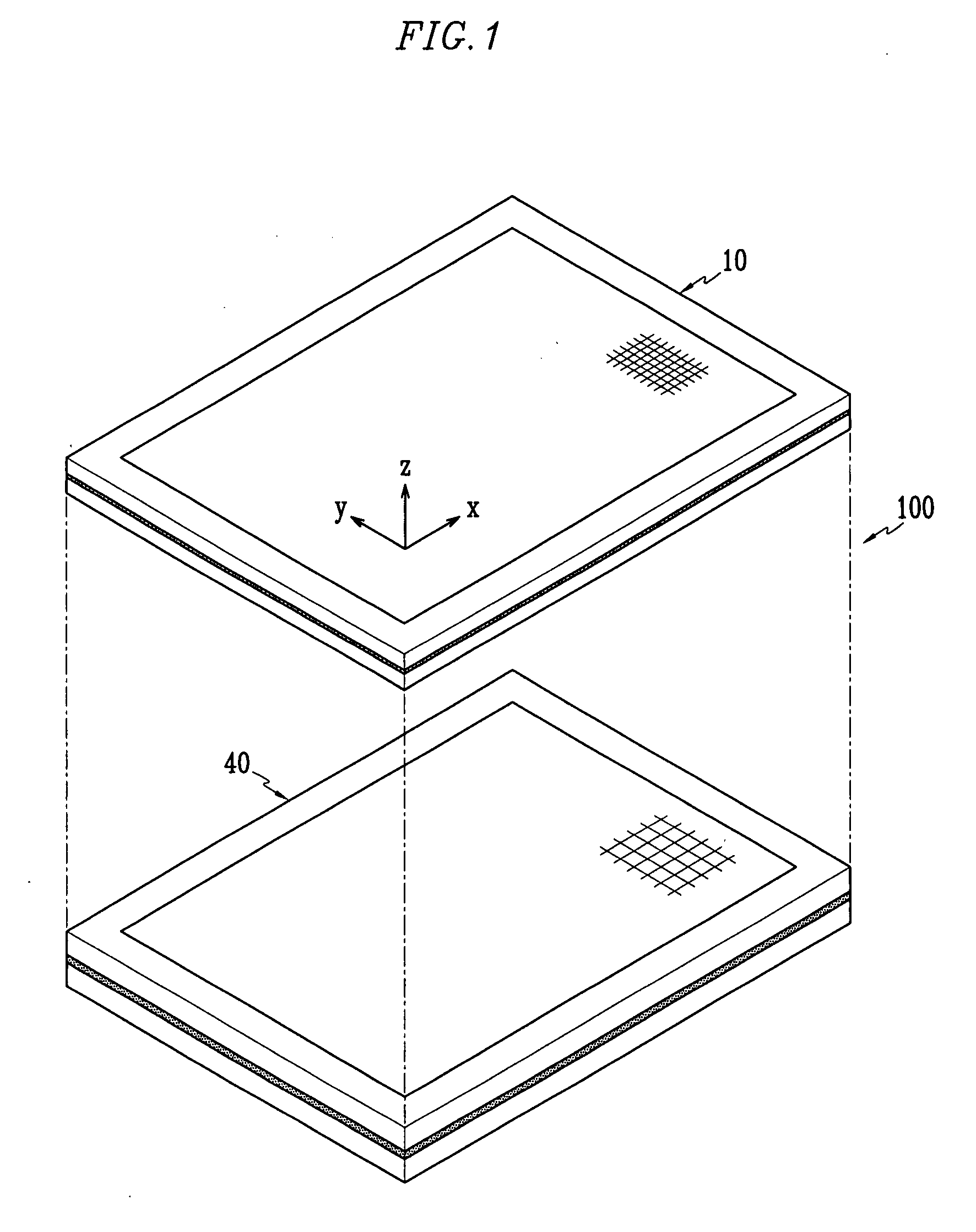
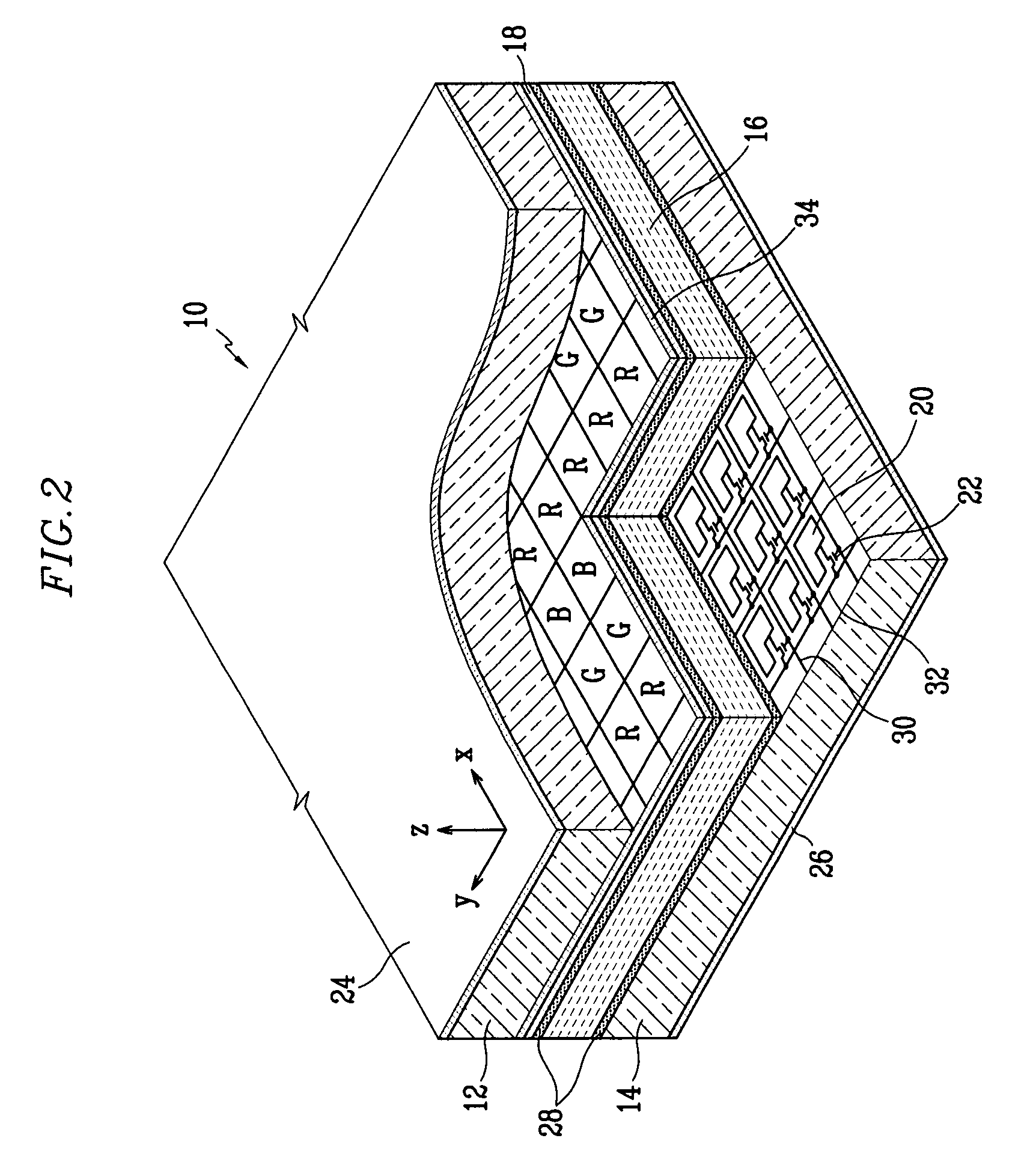
[0038]FIG. 1 is an exploded perspective view of a liquid crystal display according to an embodim...


PUM


Abstract

A display device includes a display panel assembly having a plurality of pixels arranged in rows and columns and a backlight unit disposed behind the display panel assembly and having a plurality of pixels arranged in rows and columns. The number of the pixels of the backlight unit is less than a number of the pixels of the display panel assembly. The backlight unit includes a plurality of scan electrodes arranged along one of row and column directions and a plurality of data electrodes arranged along the other of the row and column directions; and the pixels of the backlight unit are adapted to emit lights having intensities in accordance with gray levels of the pixels of the display panel assembly.

Description

CROSS-REFERENCES TO RELATED APPLICATIONS[0001]This application claims priority to and the benefit of Korean Patent Application Nos. 10-2006-0045225, 10-2006-0086145, and 10-2006-0104085 filed in the Korean Intellectual Property Office on May 19, 2006, Sep. 7, 2006, Oct. 25, 2006, respectively, the entire content of all of which is incorporated herein by reference.BACKGROUND OF THE INVENTION[0002]1. Field of the Invention[0003]The present invention relates to a display device, and more particularly, to a display device including a backlight unit that operates in synchronization with a display image, and a method for driving the display device.[0004]2. Description of Related Art[0005]A display device can be classified into a non-self-emissive device that displays an image by receiving light from a backlight unit using a light receiving element and a self-emissive device that displays an image using a self-emissive element. A liquid crystal display that is one of the non-self-emissive ...

Claims


Application Information

Patent Timeline
Patent Type & Authority Applications(United States)
IPC IPC(8): G09G3/36
CPCG09G3/3426G09G2360/16G09G2320/0626
Inventor LEE, SANG-JINKANG, SU-JOUNGLEE, JIN-HORYU, KYUNG-SUNJUNG, KYU-WONSHIN, JONG-HOONJUN, PIL-GOO
Owner SAMSUNG SDI CO LTD
Learn More