Method and Apparatus for Audio Signal Expansion and Compression
- Summary
- Abstract
- Description
- Claims
- Application Information
AI Technical Summary
Benefits of technology
Problems solved by technology
Method used
Image
Examples
first embodiment
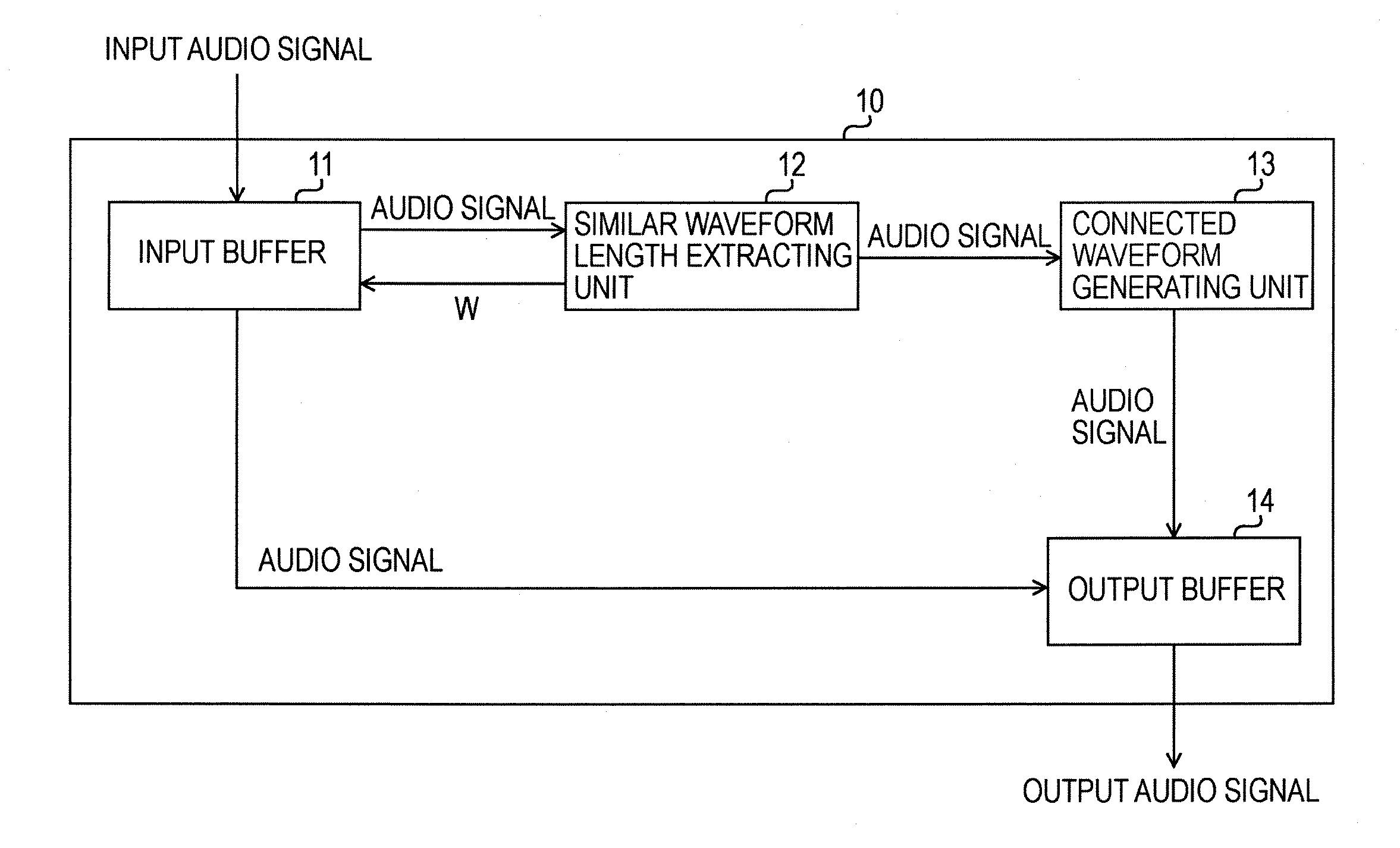
[0071]FIG. 1 is a block diagram showing an example of a configuration of an audio signal expansion and compression apparatus according to the present invention. An audio signal expansion and compression apparatus 10 has an input buffer 11, a similar waveform length extracting unit 12, a connected waveform generating unit 13, and an output buffer 14. The input buffer 11 buffers input audio signals. The similar waveform length extracting unit 12 extracts a length of similar waveforms (for 2 W samples) from the audio signal buffered in the input buffer 11. The connected waveform generating unit 13 cross-fades the audio signals for 2 W samples to generate a connected waveform for W samples. The output buffer 14 outputs an output audio signal, containing the input audio signal and a signal of the connected waveform, supplied thereto in accordance with a speech speed converting rate R.
[0072] The input buffer 11 buffers the input audio signal to be processed. As described later, the simila...
second embodiment
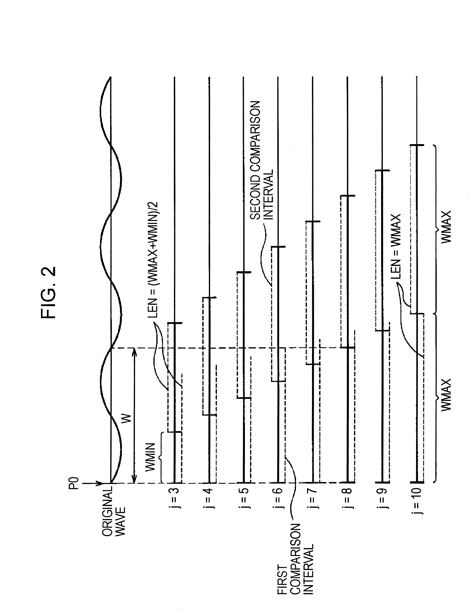
[0085] a signal comparison length LEN is set to a larger value as shown in the following equation.
LEN=WMAX (20)
[0086]FIG. 6 is a schematic diagram for illustrating a similar waveform length extracting process according to the second embodiment of the present invention. In this example, WMIN and WMAX are set equal to 3 and 10, respectively. A similar waveform length extracting unit 12 determines a value of a function D(j) while incrementing an index j by 1 from 3 to 10. Since the value of the function D(j) becomes small when the waveforms are more similar, the value of the function D(j) becomes minimum when j=8. Thus, an interval length W is set equal to 8.
[0087] A flowchart of the similar waveform length extracting process according to the second embodiment is the same as that of the similar waveform length extracting process according to the first embodiment shown in FIG. 3. A process of a subroutine that calculates the value of the function D(j) differs.
[0088] The function D...
third embodiment
[0093] a signal comparison length LEN is set to a larger value as represented by the following equation.
LEN=2WMAX−j (22)
[0094]FIG. 8 is a schematic diagram for illustrating a similar waveform length extracting process according to the third embodiment of the present invention. In this example, WMIN and WMAX are set equal to 3 and 10, respectively. A similar waveform length extracting unit 12 determines a value of the function D(j) while incrementing an index j by 1 from 3 to 10. Since the value of the function D(j) becomes smaller when the waveforms are more similar, the value of the function D(j) becomes minimum when j=8. Thus, an interval length W is set equal to 8.
[0095] A flowchart of the similar waveform length extracting process according to the third embodiment is the same as that of the similar waveform length extracting process according to the first embodiment shown in FIG. 3. A process of a subroutine that calculates the function D(j) differs.
[0096] The function D(j...
PUM
 Abstract
Description
Claims
Application Information
 - R&D
- Intellectual Property
- Life Sciences
- Materials
- Tech Scout
- Unparalleled Data Quality
- Higher Quality Content
- 60% Fewer Hallucinations
Browse by: Latest US Patents, China's latest patents, Technical Efficacy Thesaurus, Application Domain, Technology Topic, Popular Technical Reports.
© 2025 PatSnap. All rights reserved.Legal|Privacy policy|Modern Slavery Act Transparency Statement|Sitemap|About US| Contact US: help@patsnap.com


