High resolution enabling apparatus and method

Inactive Publication Date: 2007-11-22
KK TOSHIBA
View PDF6 Cites 52 Cited by
  • Summary
  • Abstract
  • Description
  • Claims
  • Application Information

AI Technical Summary

Benefits of technology

[0044]FIG. 32 is a view illustrating an example of a search range for acquiring a corresponding point, which is advantageous when the brightness varies in the horizontal direction;
[0045]FIG. 33 is a view illustrating another example of the search range for acquiring a corresponding point, which is advantageous when the brightness varies in the horizontal direction;
[0046]FIG. 34 is a view illustrating yet another example of the search range for acquiring a corresponding point, which is advantageous when the brightness varies in the horizontal di

Problems solved by technology

Although the above-described frames degradation inverse conversion method can provide a sharp high-resolution image, it requires a

Method used


Image

  • High resolution enabling apparatus and method
  • High resolution enabling apparatus and method
  • High resolution enabling apparatus and method

Examples


first embodiment

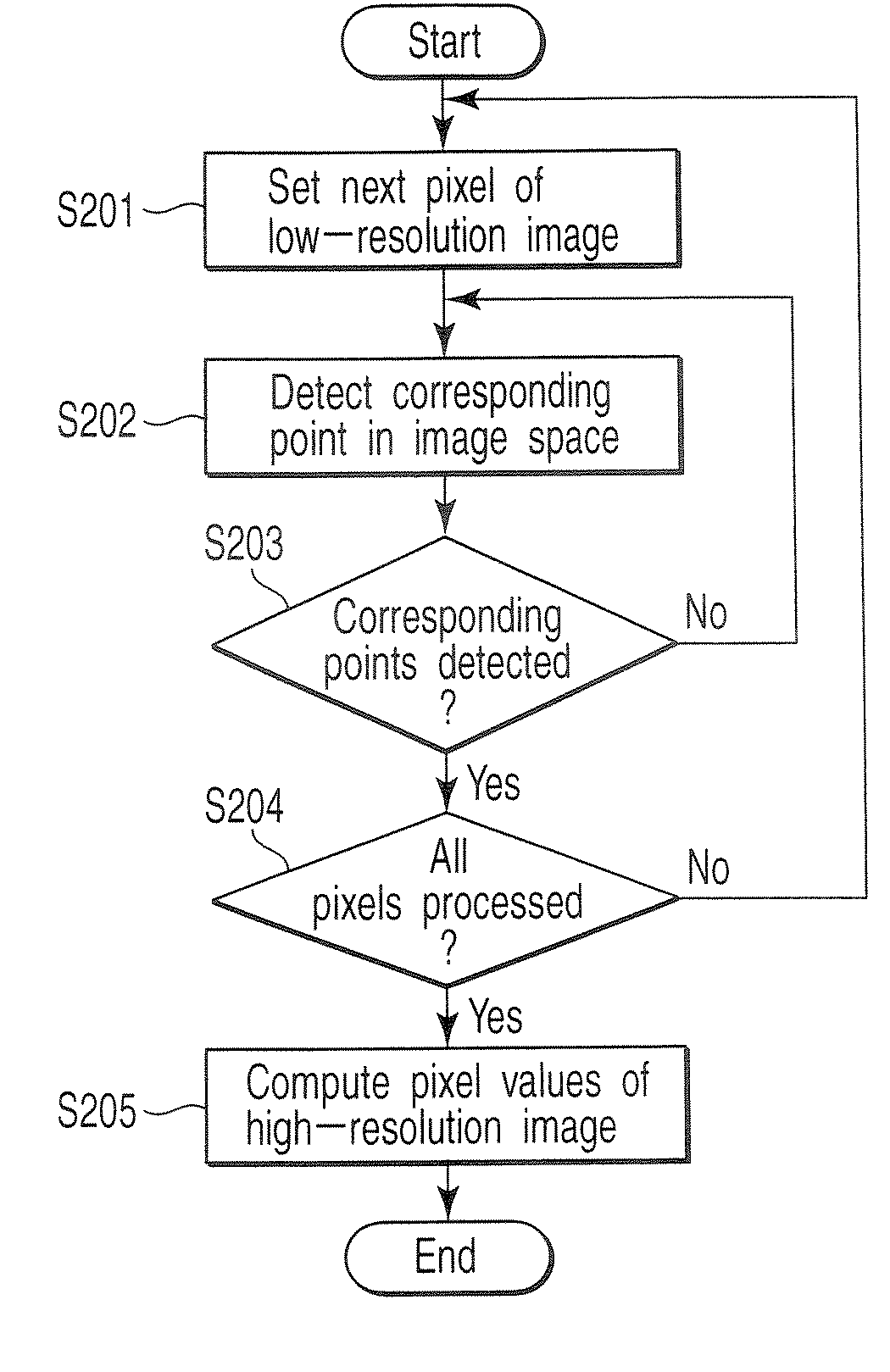
[0094]Referring now to FIG. 2, an operation example of the high-resolution enabling apparatus according to the embodiments will be described. Images may hereinafter be called frames.

[0095]At step S201, the candidate designation unit 102 sets, as target pixels, pixels in a low-resolution image in a preset order. In the case of a still image, a so-called raster order, for example, is employed, in which the target pixels are successively selected by rightward scanning horizontal pixel lines in the order beginning with the upper left pixel and ending with the lower right pixel. In the case of a moving image, frames are successively selected, and the pixels in each frame are selected in the above-mentioned raster order. The relationship between the low-resolution frame and high-resolution frame of a moving image will be described later with reference to FIGS. 3 to 8.

[0096]At step S202, the matching error computation unit 103, error comparison unit 104 and parabola fitting unit 107 detect...

second embodiment

[0175]Referring to FIGS. 50 to 58, a description will be given of a second embodiment in which local pattern autocorrelation is utilized.

[0176]FIG. 50 shows part of a still image or part of one frame of a moving image, which is input as low-resolution image 5006 for realizing high resolution. Black dots denote pixels. The hatched portion indicates a low-brightness portion, which contains edge 5007 extending from the lower left to the upper right. The edge indicates the boundary in brightness acquired before sampling and during photography. It is a matter of course that the pixels of low-resolution image 5006 exhibit only brightness. To reproduce the light and shade of edge 5007 as accurately as possible, samples values of a certain portion of a subject are acquired from different image frames of the subject in the conventional art. However, as described above referring to FIG. 17, five lines 5001 to 5005 enclosed by the broken lines in FIG. 50 should have very similar brightness cha...

third embodiment

[0198]Referring to FIGS. 59 and 60, a description will be given of a third embodiment in which when local pattern autocorrelation is utilized, blocks are used instead of lines.

[0199]As shown in FIG. 59, an image of (9×9) pixels is divided into blocks 5901 of (3×3) pixels, and one of the blocks 5901 is used as reference block 5902 in which points (corresponding points) corresponding to the pixels of the other blocks are determined.

[0200]Referring to the flowchart of FIG. 60, the operation of the third embodiment will be described.

[0201]At step S6001, an end block included in the blocks, into which the image space is divided, is set as a reference block subjected to first realization of high resolution. Then, the program proceeds to step S4801.

[0202]At step S4801, the number n assigned to a low-resolution block used for realizing high resolution of the set reference block is set to 1. Subsequently, the program proceeds to step S6002. In FIG. 59, block 5902 is set as the reference bloc...


PUM


Abstract

An apparatus includes unit acquiring, from an image source, an image represented by pixel values indicating brightness levels, unit setting, as a reference frame, one frame, unit sequentially setting, to be target pixels, each of pixels in one or more frames, unit setting target-image regions including the target pixels, unit searching the reference frame for similar-target-image regions similar to each of the target-image regions in a change pattern of pixel values, unit selecting, from the similar-target-image regions, corresponding points corresponding to each of the target pixels, unit setting sample values concerning brightness at the corresponding points to a pixel value of a target pixel corresponding to the corresponding points, and unit computing pixel values in a high-resolution image corresponding to the reference frame, based on the sample values and the corresponding points, the high-resolution image containing a larger number of pixels than pixels in the reference frame.

Description

CROSS-REFERENCE TO RELATED APPLICATIONS[0001]This application is based upon and claims the benefit of priority from prior Japanese Patent Application No. 2006-142074, filed May 22, 2006, the entire contents of which are incorporated herein by reference.BACKGROUND OF THE INVENTION[0002]1. Field of the Invention[0003]The present invention relates to a high resolution enabling apparatus and method for converting, into image data of higher resolution, image data acquired by photography using a camera, or received by a TV set.[0004]2. Description of the Related Art[0005]TV sets and displays of a large number of pixels, i.e., of high resolution, have recently been spread. When an image is displayed on a TV set or display, the number of pixels included in image data is converted into the number of pixels included in the panel. In particular, in high resolution enabling conversion in which the number of pixels is increased, a frames degradation inverse conversion method is known as a method...

Claims


Application Information

Patent Timeline
IPC IPC(8): G06K9/32
CPCH04N7/0125G06T3/4053
Inventor IDA, TAKASHIISOGAWA, KENZOMATSUMOTO, NOBUYUKIKANEKO, TOSHIMITSUTAKESHIMA, HIDENORI
Owner KK TOSHIBA
Why Eureka
Try Eureka