Robot trajectory control including emergency evacuation path system and method

a robot and trajectory control technology, applied in the direction of electric programme control, program control, instruments, etc., can solve the problem of difficulty for someone to manually use the control to move the robot, and achieve the effect of reducing the number of safety paths

Inactive Publication Date: 2007-06-21
KUKA LAB GMBH
View PDF15 Cites 28 Cited by
  • Summary
  • Abstract
  • Description
  • Claims
  • Application Information

AI Technical Summary

Benefits of technology

[0010] Each position on the path may have a plurality of safe position(s) associated with that it can move to. This can be done with a unique safety path for each point of the robot main path. Ideally, a unique safety path would exist for each unique position in the ride path. However, to save on the total data (to address memory constraints) this may not be practical to save and make available for execution the safety path for each point on the main path. As such groups of points on the robot main path are associated with a safety path, namely when the safety path is executed, the first point on the safety path is in common to several points on the robot main path. Further, two or more safety paths may share points, with all safety paths advantageously sharing the final safety point or unload point. The user may create unique safety paths throughout the entire path. The unique safety paths would allow the user to create specialized paths that take into account obstacles, adjacent robots and orientation of the robot itself. Safety paths for groups of positions in the path table is an approach which reduces the number of safety paths the programmer would be required to teach the robot. One version of this is to provide special markers that can be added into the path table that indicates which safety path should be active for the following set of points on the main path or ride path. Then during the execution of the main path the underlying control system (Path Table manager for example) will keep track of the safety path that is active based on the position of the robot. When the user triggers the execution of the current safety path, the robot will move to the position as defined by the currently active safety marker.

Problems solved by technology

The problem is that the user requires the ability to move the robot from any position on the path to a safe position off of the path without coming into contact with the environment, or adjacent robots.
It can be difficult for someone to use a control to move the robot manually without colliding with the environment.
This may be due to the size of the robot and its proximity to the environment.

Method used


Image

  • Robot trajectory control including emergency evacuation path system and method
  • Robot trajectory control including emergency evacuation path system and method
  • Robot trajectory control including emergency evacuation path system and method

Examples


Embodiment Construction

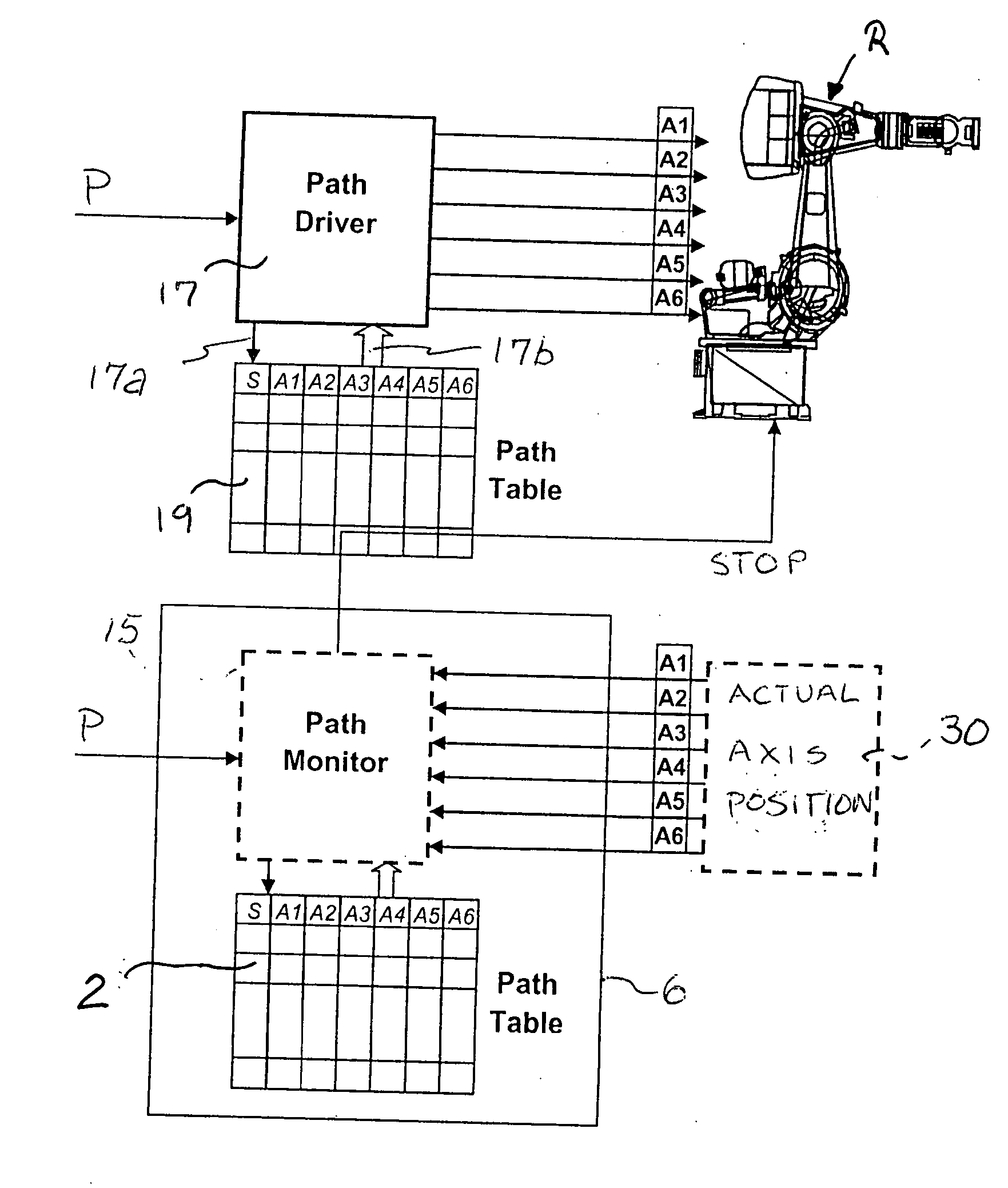
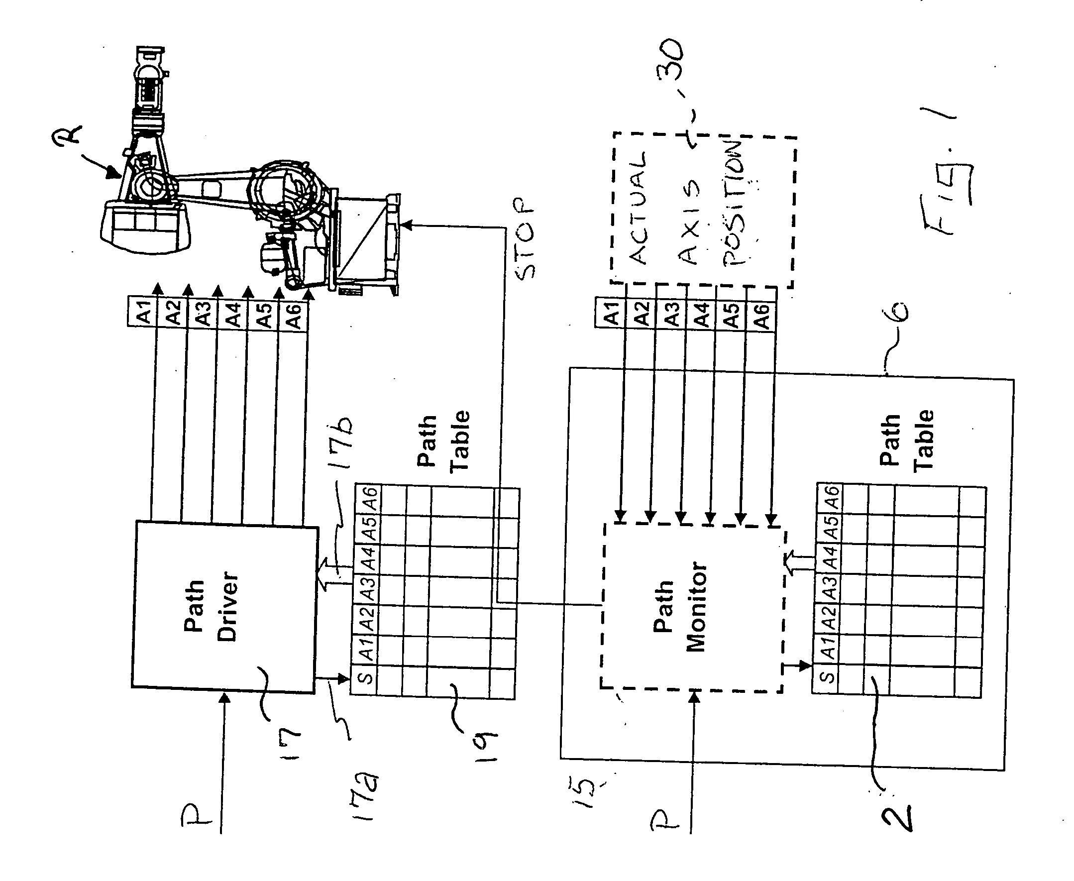
[0021] Referring to the drawings in particular, the system and method are based on a robot (multiaxial robot with turntable) R as shown in FIG. 1 using a path table 2 which is generated off-line by one or more programmers taking into account turntable information (i.e., the information on the position of the turntable) as the motion about a principal axis, about which the robot moves. This motion may be eccentric (as in the case of a carousel), while the motions of the robot axes, six axes in a conventional robot, depend on the principal motion of the turntable with this relationship being defined in the path table 2 to define a main path (also referred to as travel path and main ride path). Instead of a turntable axis as the principal axis, a linear axis may be provided as well. Moreover, the basic motion may also be a more complex motion than a rotary motion about a principle axis or than a linear motion along a principal axis; what is essential is a preset path of motion with pos...


PUM


Abstract

A system and process is provided for controlling a robot path of a robot including providing a main path for movement of the robot based on path data having points along the main path and providing a safe evacuation path from each point in the main path to get to a safe position. The main path is formed with safety evacuation path considerations in mind such that along any point on ride path the robot can be safely moved to a safety point or to the unload position or safe position.

Description

[0001] The invention relates generally to multi-axis robot systems such as robots according to EN ISO 8373, subsection 2.6 and more particularly to robot path control providing procedures for emergency stopping including safe evacuation paths for emergency stopping positions. BACKGROUND OF THE INVENTION [0002] Robot control systems typically provide for an emergency stop (E-Stop), to halt the multi-axial robot in an emergency situation. Usually, pressing of E-Stop results in the robot following a category 0 or 1 stop. Even after stopping the robot along the normal trajectory of the robot, there are situations that require the robot to be moved off the normal trajectory path to a safe position within the workspace of the robot. [0003] The problem is that the user requires the ability to move the robot from any position on the path to a safe position off of the path without coming into contact with the environment, or adjacent robots. The robot needs to move in a controlled manner to ...

Claims


Application Information

Patent Timeline
Patent Type & Authority Applications(United States)
IPC IPC(8): G06F19/00
CPCB25J9/1664B25J9/1674G05B2219/40521G05B2219/50109
Inventor VOLCIC, EDWARDMIRZA, KHALID
Owner KUKA LAB GMBH
Why Eureka
Try Eureka