Device and method for mri-guided breast interventions

a technology of guiding devices and breast implants, applied in the field of mechanical positioning devices, can solve the problems of up to 5 mm probe-tip positioning errors, and achieve the effect of improving the accuracy of probe localization

Active Publication Date: 2009-10-15
MRI ROBOTICS
View PDF17 Cites 31 Cited by
  • Summary
  • Abstract
  • Description
  • Claims
  • Application Information

AI Technical Summary

Benefits of technology

[0012]In some embodiments, the present invention provides a new MR image-guided interventional (IGI) system with 3D probe-positioning capability and fitted with a custom breast coil (the coil being a portion of the image-data-gathering antenna and electronics subsystem of an MRI machine). To improve the accuracy of probe localization, graphic tools and real-time image guidance is incorporated to calculate the best point of access to the lesions and to verify probe location.

Problems solved by technology

However, both of these designs are built upon using only bilateral compression plates to stabilize the breast.
Not only does this limit access to the breast, there may be movement of the target between uncompressed and compressed states, thereby requiring repositioning and reimaging.
However, backlash in the rotation joint may incur probe-tip-positional errors of up to 5 mm at a distance of 40 mm from the rotation axis, which may occur for women with large breasts.

Method used


Image

  • Device and method for mri-guided breast interventions
  • Device and method for mri-guided breast interventions
  • Device and method for mri-guided breast interventions

Examples


Embodiment Construction

[0041]In the following detailed description of the preferred embodiments, reference is made to the accompanying drawings that form a part hereof, and in which are shown by way of illustration specific embodiments in which the invention may be practiced. It is understood that other embodiments may be utilized and structural changes may be made without departing from the scope of the present invention.

[0042]The leading digit(s) of reference numbers appearing in the Figures generally corresponds to the Figure number in which that component is first introduced, such that the same reference number is used throughout to refer to an identical component which appears in multiple Figures. Signals and connections may be referred to by the same reference number or label, and the actual meaning will be clear from its use in the context of the description.

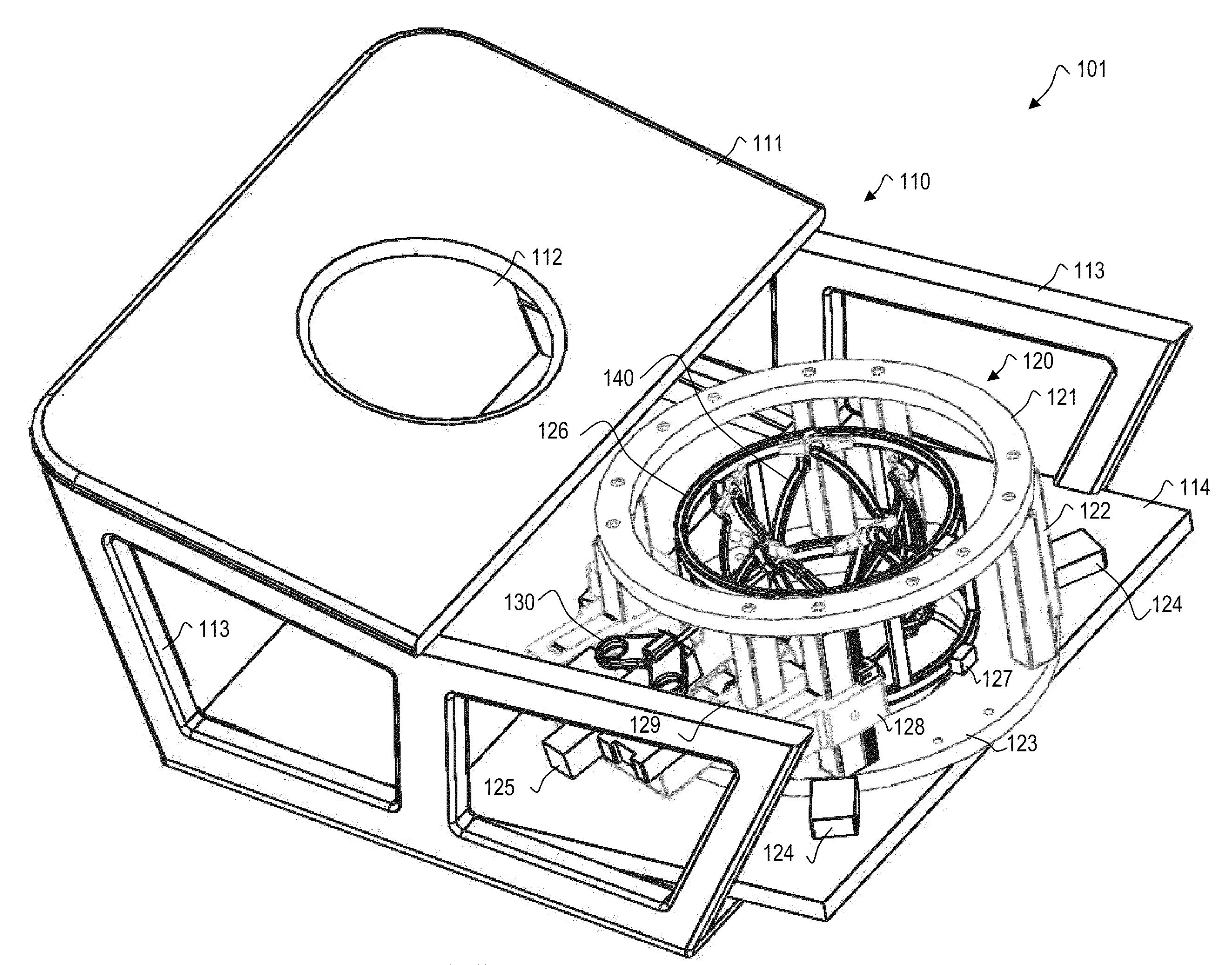
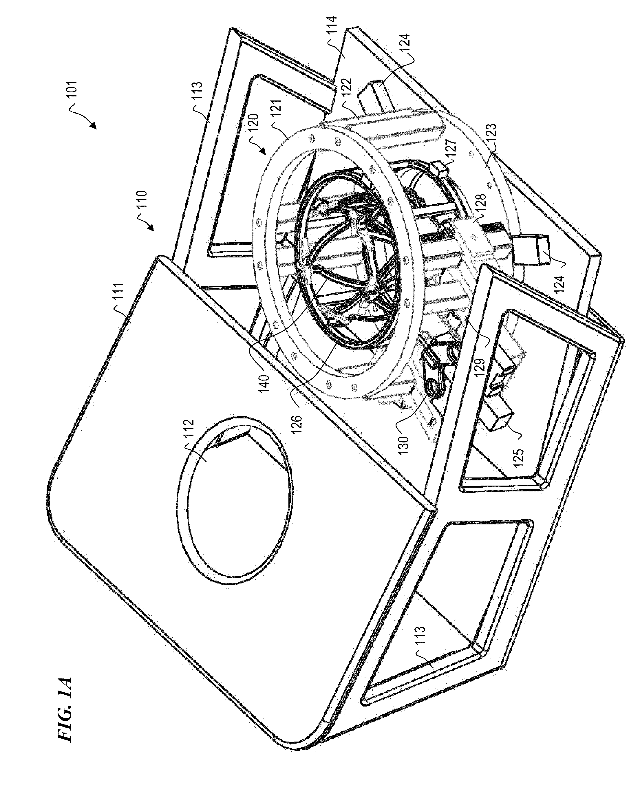
[0043]FIG. 1A is a perspective view of MRI-guided breast intervention system 101, according to some embodiments of the present invention. In s...


PUM

PropertyMeasurementUnit
strength magnetic fieldaaaaaaaaaa
distanceaaaaaaaaaa
distanceaaaaaaaaaa

Abstract

A method and apparatus for radially compressing bodily tissue and performing medical procedures from a selected one of a plurality of circumferential positions and angles, a selected one of a plurality of different elevations and elevational angles. Some embodiments include a tissue-compression fixture having members that are configured to be moved to radially compress bodily tissue such that each of a plurality of areas of biological tissue are exposed between the plurality of members, and wherein the fixture is compatible with use in an MRI machine in operation; an actuator having a receiver for a medical-procedure probe; and a computer system operatively coupled to the actuator to move the probe. The computer receives user commands, and based on the commands, moves the actuator to a selected one of a plurality of different positions around the tissue-compression fixture and then extends the probe into the patient.

Description

CROSS-REFERENCE TO RELATED APPLICATIONS[0001]This invention claims benefit under 35 U.S.C. §119(e) of U.S. Provisional Patent Application No. 61 / 124,058 titled “Device for MRI-guided Breast Intervention” and filed Apr. 14, 2008; U.S. Provisional Patent Application No. 61 / 124,057 titled “Breast Stabilization Device” and filed Apr. 14, 2008; and of U.S. Provisional Patent Application No. 61 / 168,559, filed Apr. 11, 2009, which are each hereby incorporated herein in their entirety by reference.[0002]This invention is related to U.S. patent application Ser. No. 12 / ______, titled “TISSUE-STABILIZATION DEVICE AND METHOD FOR MEDICAL PROCEDURES” filed on even date herewith by the inventors of the present invention, which is hereby incorporated herein in its entirety by reference.STATEMENT REGARDING FEDERALLY SPONSORED RESEARCH OR DEVELOPMENT[0003]The U.S. Government has a paid-up license in this invention and the right in limited circumstances to require the patent owner to license others on...

Claims


Application Information

Patent Timeline
Patent Type & Authority Applications(United States)
IPC IPC(8): A61B10/02A61B5/055
CPCA61B5/0555Y10T29/49904A61B19/201A61B2017/3409A61B2019/205A61B6/0435A61B8/406B65D2519/00059B29C65/7802B23Q39/00A61B5/055G01B21/00G01R33/30Y10T29/49764A61B10/0233A61B10/0041A61B10/0266A61B2010/0208A61B2010/045A61B90/11A61B90/17Y10T29/49947A61B5/708A61B2090/374G01R33/286G01R33/48G01R33/5608
Inventor LARSON, BLAKE TIMOTHYERDMAN, ARTHUR GUY
Owner MRI ROBOTICS
Why Eureka
Try Eureka