

Image-forming device for suppressing vibration of guide plate and jams of recording sheet
- Summary
- Abstract
- Description
- Claims
- Application Information
AI Technical Summary
Benefits of technology
Problems solved by technology
Method used
Image

Examples
first embodiment
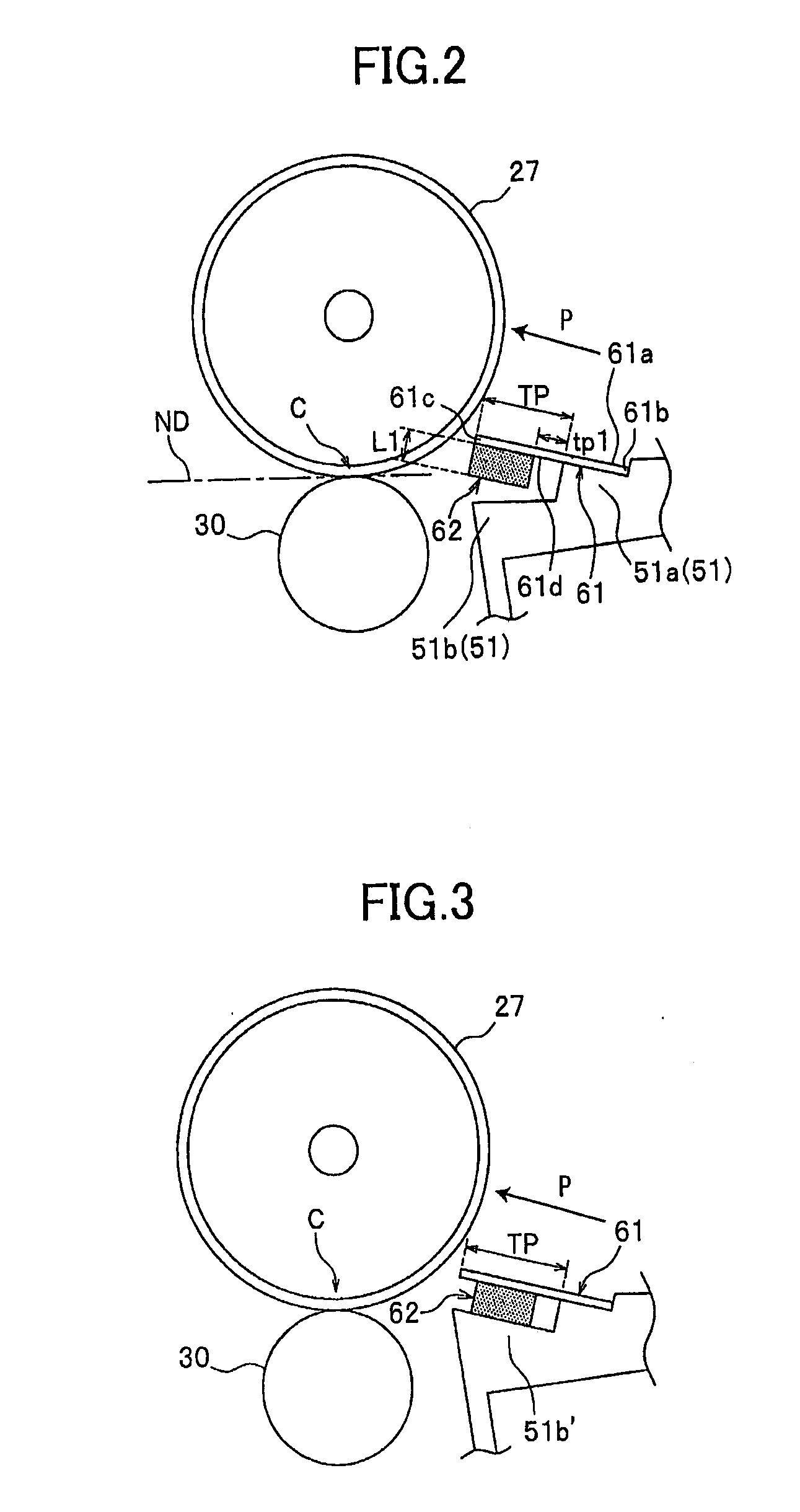
[0067]FIG. 3 shows the structure around the transfer position C according to a variation 1A in which the sponge 62 is fixed to a second seat 51b′. Specifically, the sponge 62 is fixed to the guide plate 61 and fixed to the second seat 51b′ so as to leave portions of the guide plate 61 uncovered in the upstream and downstream ends of the deformable region TP. The top surface of the second seat 51b′ is formed substantially parallel to the guide plate 61 slops relative to the nip conveying direction ND or the reference plane.
[0068] The structure according to variation 1A described above has the following effects.
[0069] By fixing the sponge 62 to the second seat 51b′, the sponge 62 can rapidly damp vibrations in the guide plate 61. Further, since the sponge 62 is fixed to the guide plate 61 so as not to occupy the entire deformable region TP of the guide plate 61, the guide plate 61 can retain sufficient flexibility.
[0070]FIGS. 4A and 4B show the structure around the transfer positio...
second embodiment
[0101] The structure described above has the following effects.
[0102] The sponge 69 provided on the guide plate 61 absorbs vibrations in the guide plate 61 when the trailing edge of the paper 3 leaves the guide plate 61, thereby suppressing flapping noise in the guide plate 61.
[0103] By forming the sponge 69 with a thickness that gradually increases from the upstream side toward the downstream side, the portion of the deformable region TP of the guide plate 61 bends easier on the base end portion 61b side. Hence, the guide plate 61 retains flexibility in this region, suppressing the occurrence of paper jams.
[0104] Further, since the thickest portion of the sponge 69 is located on the downstream end 61c of the guide plate 61, the sponge 69 can effectively absorb flapping noise produced by the downstream end 61c of the guide plate 61.
[0105] The present invention is not limited to the structure according to the second embodiment, but may be applied to any structure in which the thi...
third embodiment
[0112] The structure of the third embodiment described above has the following effects. The sponges 70 and 71 provided on the guide plate 61 can absorb vibrations in the guide plate 61 produced when the trailing edge of the paper 3 leaves the guide plate 61, thereby suppressing flapping noise in the guide plate 61.
[0113] Forming the sponge 70 softer than the sponge 71 allows the guide plate 61 to bend more freely on the downstream end 61c to which the sponge 70 is fixed, thereby ensuring that this portion of the guide plate 61 can bend easily to suppress the occurrence of paper jams.
[0114] Further, since the downstream end 61c of the guide plate 61 can bend easily, the paper 3 can be placed suitably close to the photosensitive drum 27.
[0115] The third embodiment is particularly effective when both sponges do not have the same balance of softness and vibration-absorbing capacity. For example, it is effective to form the sponge 70 of a softer material that has a poor vibration-absor...
PUM
 Abstract
Description
Claims
Application Information