
Window blind assembly

Inactive Publication Date: 2007-11-29
HUANG TAI LONG
View PDF9 Cites 6 Cited by
  • Summary
  • Abstract
  • Description
  • Claims
  • Application Information

AI Technical Summary

Benefits of technology

[0006]Therefore, the object of the present invention is to provide a window blind assembly that can be easily assembled and disassembled and that has specific components fixed in form so as to largely minimize production costs and so as to reduce troublesome assembly operations.

Problems solved by technology

Hence, cleaning and replacement of the blind unit 2 is very inconvenient.

Method used


Image

  • Window blind assembly
  • Window blind assembly
  • Window blind assembly

Examples


Embodiment Construction

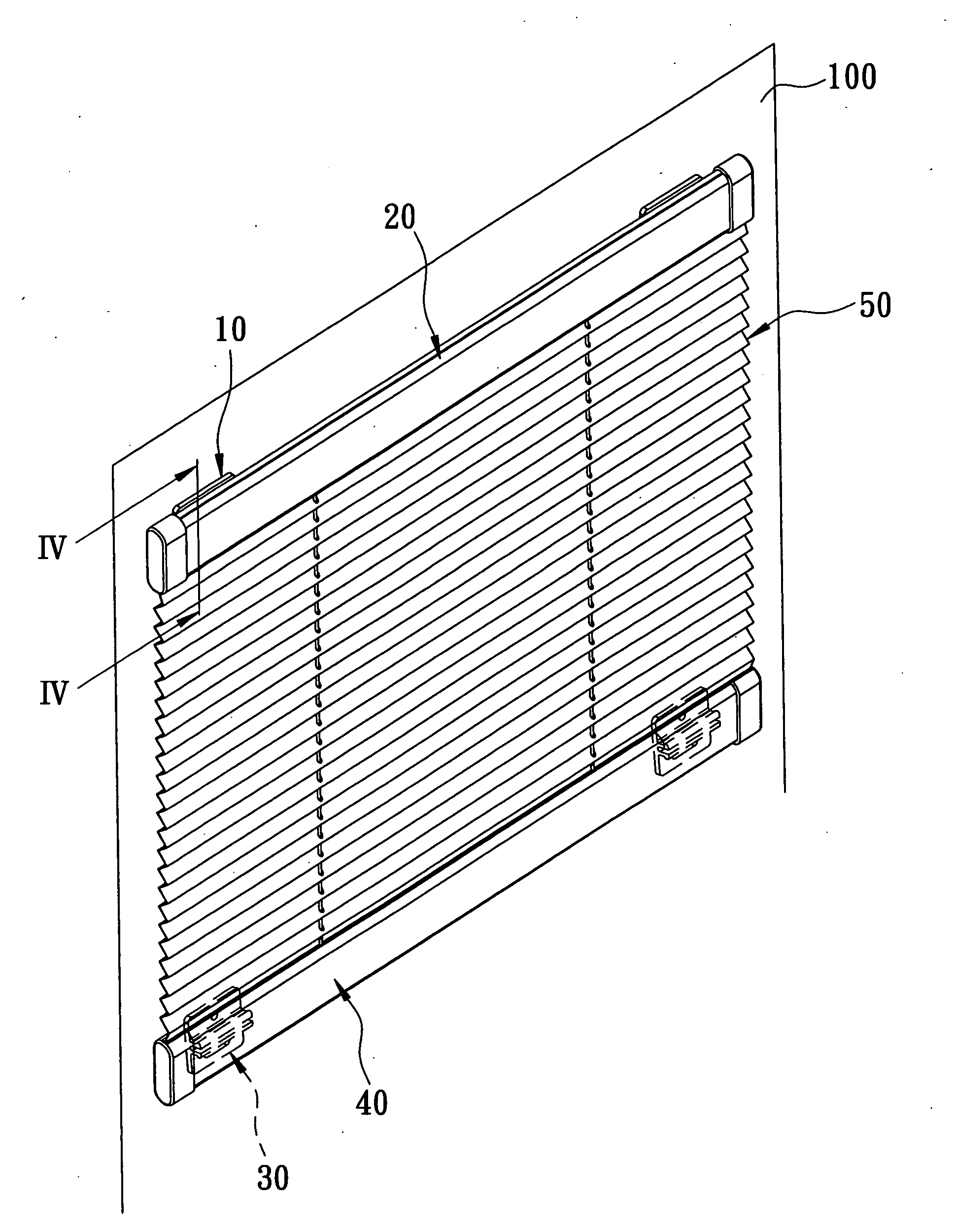
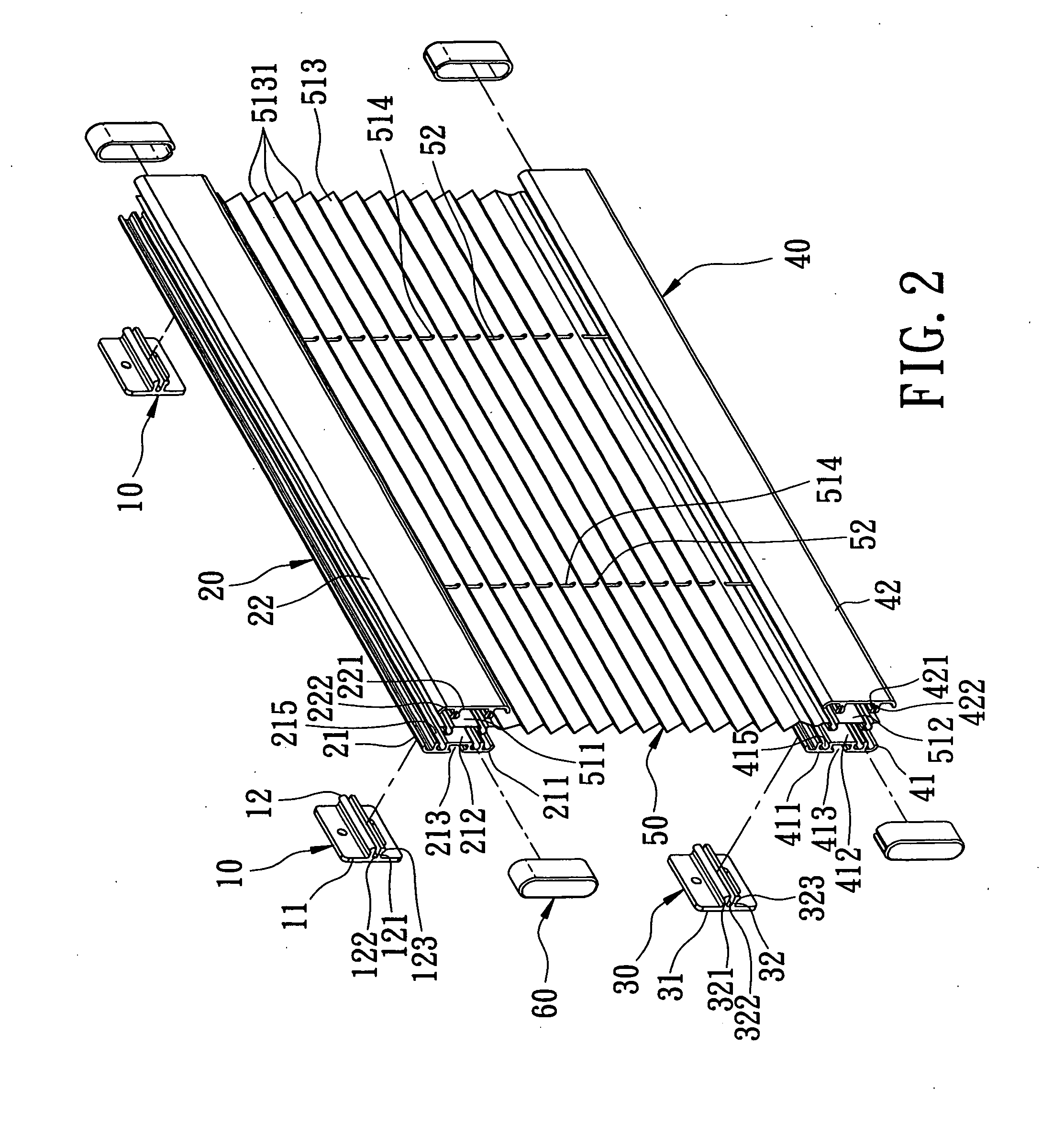
[0014]Referring to FIGS. 2 to 5, the preferred embodiment of a window blind assembly according to the present invention is shown to include two top fixing seats 10, two bottom fixing seats 30, a headrail 20, a bottom rail 40, and a blind unit 50.

[0015]Each of the top and bottom fixing seats 10, 30 has a base plate 11, 31 adapted to be fixed to a wall 100 (see FIGS. 3 and 5) by use of double-sided adhesive tape or nails, and a first engaging portion 12, 32 projecting outwardly from the base plate 11, 31. The first engaging portion 12, 32 of each of the top and bottom fixing seats 10, 30 is in the form of a longitudinal first protrusion, and includes two spaced-apart first spring plates 121, 321 that extend longitudinally to define a slot 122, 322 therebetween so as to permit biasing movement of the first spring plates 121, 321 toward or away from each other. The first spring plates 121, 321 respectively have oppositely projecting butt ends 123, 323.

[0016]Each of the headrail 20 and t...


PUM


Abstract

A window blind assembly includes top and bottom fixing seats adapted to be fixed to a support and having a first engaging portion, a headrail, a bottom rail, and a blind unit. Each of the headrail and bottom rail includes a pair of first and second clamp plates having opposite inner faces, and protrusion-and-groove engagement surfaces formed on the inner faces. One of the first and second clamp plates further has a first retaining portion to engage the first engaging portion. The blind unit has top and bottom end portions. Each of the top and bottom end portions is clamped detachably between the inner faces and between the protrusion-and-groove engagement surfaces of one of the headrail and the bottom rail.

Description

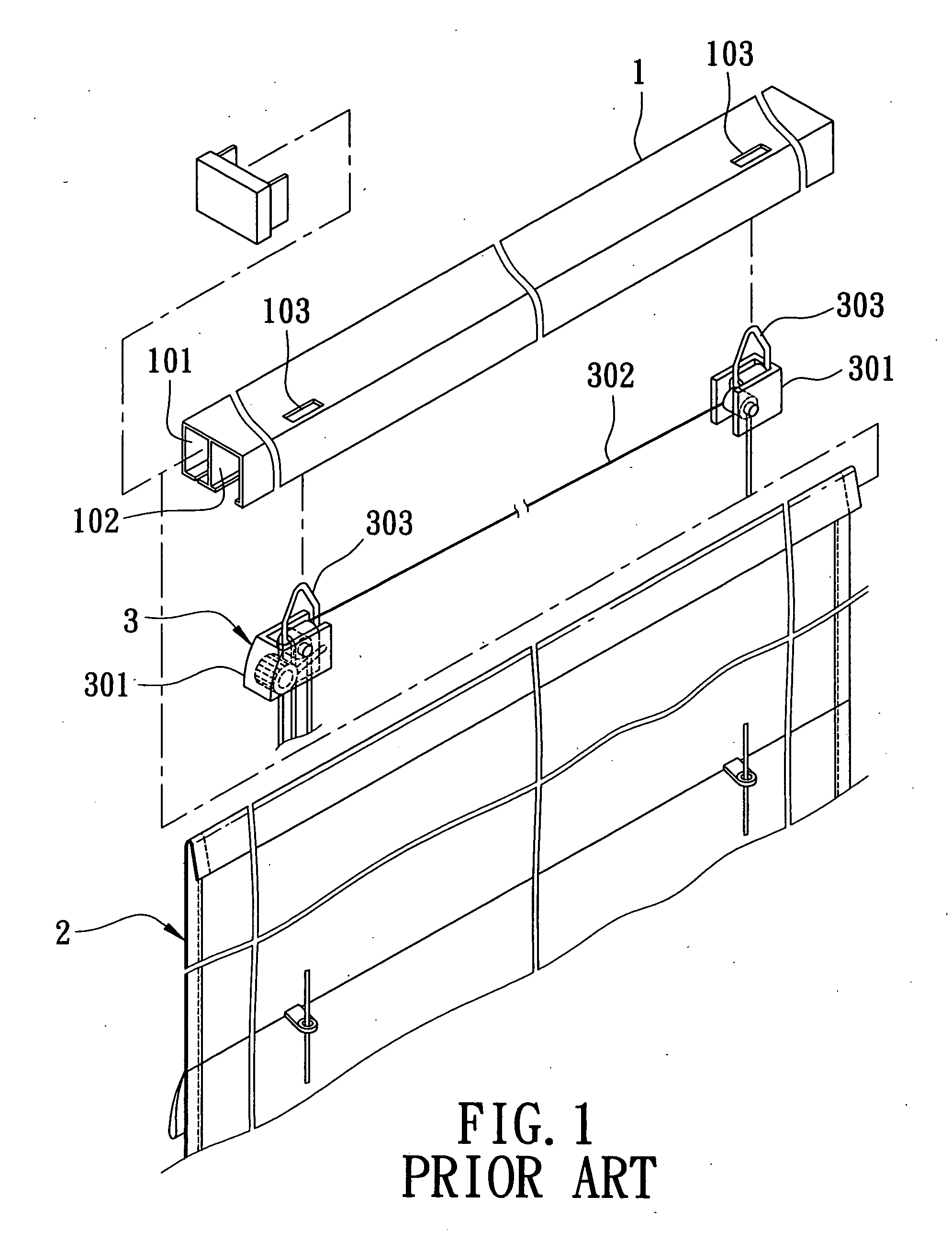
BACKGROUND OF THE INVENTION[0001]1. Field of the Invention[0002]The invention relates to a window blind, more particularly to a window blind assembly that can be easily assembled and disassembled.[0003]2. Description of the Related Art[0004]Referring to FIG. 1, a conventional window blind assembly includes a headrail 1, a blind unit 2, and a control unit 3. The headrail 1 includes a first chamber 101, a second chamber 102, and two spaced-apart through holes 103 provided in a top wall-of the headrail 1. The blind unit 2 is inserted slidably and longitudinally into the first chamber 101. The control unit 3 is installed in the second chamber 102, and includes two drums 301, a cord 302 extending between the drums 301 and associated with the blind unit 2 in a conventional manner, and two ring members 303 provided respectively on the drums 301 and extending respectively through the through holes 103. The ring members 303 are used to hang the conventional window blind assembly.[0005]Althou...

Claims


Application Information

Patent Timeline
IPC IPC(8): A47H5/00
CPCE06B9/262E06B2009/2625E06B9/324E06B9/266
Inventor HUANG, TAI-LONG
Owner HUANG TAI LONG
Learn More