
Wavelength-division multiplex system and a method of automatically setting conversion wavelengths of such a system

Inactive Publication Date: 2007-08-21
FUJITSU LTD
View PDF4 Cites 0 Cited by
  • Summary
  • Abstract
  • Description
  • Claims
  • Application Information

AI Technical Summary

Benefits of technology

[0027]Accordingly, it is a general object of the present invention to provide a WDM device in which a process of setting wavelengths λ for wavelength-converting parts can be performed without manual operations.
[0036]With the WDM devices and methods described above, erroneous setting of wavelength λ can be prevented. Also, since the operator's intervention is reduced, reliability of the wavelength setting operation can be improved. Also, troublesome operation is reduced and convenience of the operation is improved.

Problems solved by technology

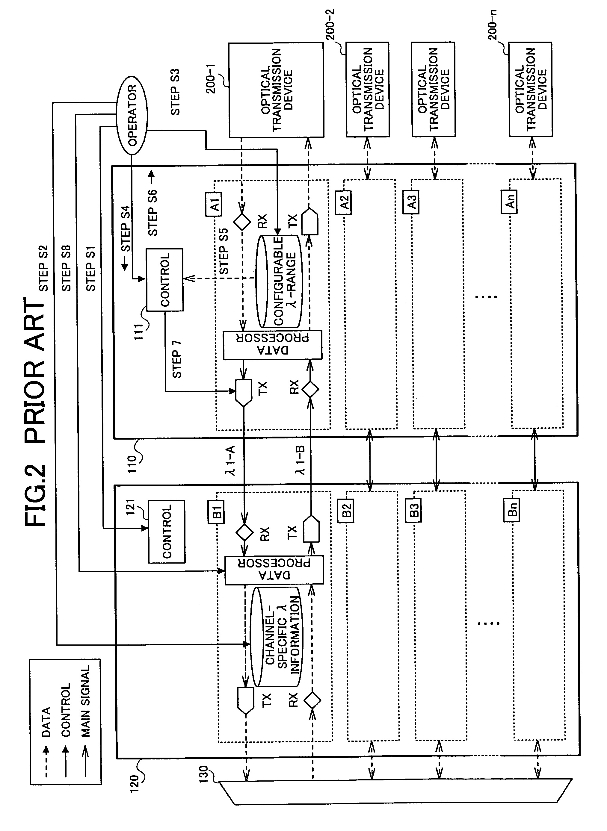
There are several drawbacks with such a wavelength-setting operation of the related art.
Second, the wavelength-setting operation of the related art requires many steps of complicated manual operations by the operator.
This may result in man-caused erroneous operations.
Therefore, it requires considerable efforts by the operator.
Fourth, according to the wavelength setting operation of the related art, the operator is not informed of alteration of connected channels.
Therefore, the user may try to transmit signals using an erroneously specified wavelength.

Method used


Image

  • Wavelength-division multiplex system and a method of automatically setting conversion wavelengths of such a system
  • Wavelength-division multiplex system and a method of automatically setting conversion wavelengths of such a system
  • Wavelength-division multiplex system and a method of automatically setting conversion wavelengths of such a system

Examples


first embodiment

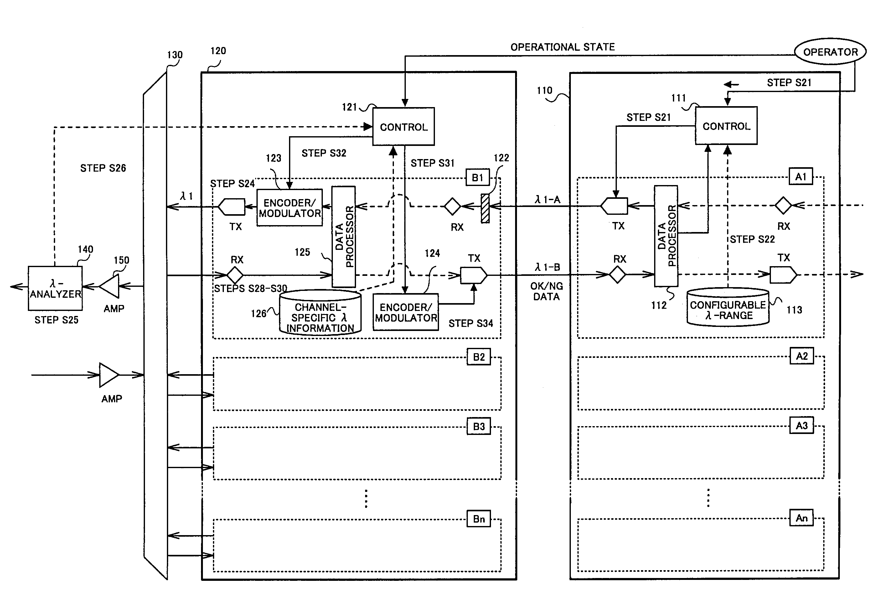
[0080]FIG. 6 is a block diagram showing a configuration of the WDM device of the present invention. As shown in the figure, the WDM device includes the wavelength-converting unit 110, the wavelength interface unit 120 and the MUX / DEMUX 130. The wavelength-converting unit 110 is connected to optical transmission devices so as to receive signals to be multiplexed and to convert wavelengths of the received signals. The wavelength interface unit 120 performs ON / OFF control of the signals received from the wavelength-converting unit 110 at predetermined timings. The MUX / DEMUX 130 multiplexes the plurality of signals from the wavelength interface unit 120 and transmits the multiplexed signals to an optical fiber. The MUX / DEMUX 130 may be replaced by a multiplexer if the WDM device is only used for transmitting signals.

[0081]FIG. 6 shows that the wavelength-converting unit 110 includes the wavelength-converting subunits A1, . . . , An, each converting the wavelength of the signal received ...

second embodiment

[0108]the present invention will be described below.

[0109]FIG. 10 is a diagram showing a WDM device of the second embodiment of the present invention. In this embodiment, as shown in the figure, the wavelength-converting unit 110 is further provided with a retry count monitoring part 114. A retry determination part 115 is provided in each of the wavelength-converting subunits Ax. An operation of the second embodiment will be described with reference to the flowchart shown in FIG. 11.

[0110]It is to be noted that operational requirements of the second embodiment are the same as those of the first embodiment.

[0111]In a similar manner to the first embodiment, the operator inputs a DATA output request to the control part 111 of the wavelength-converting unit 110 (step S41). Then, a trial counter (retry_count) is initialized (step S42).

[0112]Thereafter, while performing the process of FIG. 7, the retry determination part 115 of the wavelength-converting subunit Ax monitors the data-proces...

third embodiment

[0116]the present invention will be described below.

[0117]FIG. 12 is a diagram showing a WDM device of the third embodiment of the present invention. In this embodiment, as shown in the figure, the wavelength-converting unit 110 is further provided with a third storage part 116 for storing wavelengths λ that has already been set. An operation of the second embodiment will be described with reference to the flowchart shown in FIG. 11. An operation of this embodiment will be described with reference a flowchart shown in FIG. 13.

[0118]It is to be noted that operational requirements of the third embodiment are the same as those of the first embodiment.

[0119]Upon initializing the wavelength-converting unit 110, a third storage part 116 is initialized (step S51).

[0120]At the wavelength-converting subunit Ax, a relevant wavelength λx is automatically determined in accordance with the process shown in FIG. 7 (steps S52 through S55).

[0121]The determined wavelength λx is stored in the third s...


PUM


Abstract

For a WDM device including a multiplexer receiving fixed wavelengths, wavelength-converting parts for converting input wavelengths from optical transmission devices into the fixed wavelengths, and interface parts provided between the multiplexer and the wavelength-converting parts and having a specific wavelength that matches the fixed wavelength of the multiplexing part, a method and a device is provided for automatically determining the specific wavelength of the interface part that is to be selected as a converted wavelength output from the wavelength-converting part.

Description

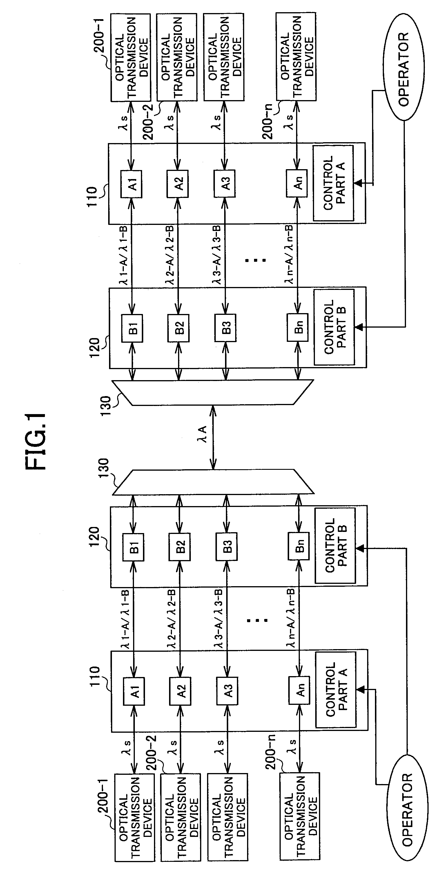
BACKGROUND OF THE INVENTION[0001]1. Field of the Invention[0002]The present invention relates to a wavelength-division multiplex system that enables an efficient use of optical fibers and particularly to an improved method of setting wavelengths to be allocated to each transmission channel in such a wavelength-division multiplex system.[0003]Recently, optical transmission systems provided with lines with larger capacity are being developed. Wavelength-division multiplexing (WDM) technology is becoming of an interest as a technology that is necessary for making efficient use of optical fibers.[0004]FIG. 1 is a diagram showing an example of a WDM system. In the example shown in FIG. 1, the WDM system includes two WDM devices connected to each other. Each of the WDM devices includes a wavelength-converting unit (λ-converter) 110, a wavelength interface unit (I / F) 120 and a wavelength multiplexer / demultiplexer (MUX / DEMUX) 130. The wavelength-converting unit 110 receives signals of wavel...

Claims


Application Information

Patent Timeline
IPC IPC(8): H04J14/02H04J14/00H04B10/07H04B17/00
CPCH04J14/0226H04J14/0282H04J14/0246H04J14/025
Inventor KAWAKAMI, KOUJIKIKUTA, KAZUTAKAHARA, SHINGO
Owner FUJITSU LTD
Learn More