Vehicle and control method of vehicle

a technology of vehicle and control method, which is applied in the direction of braking system, braking components, transportation and packaging, etc., can solve the problems of driver discomfort in the braking state of the vehicle, the difference in braking force between the two hydraulic systems, and the pair of left and right, so as to reduce such a potential difference in braking force

Inactive Publication Date: 2007-11-29
TOYOTA JIDOSHA KK
View PDF9 Cites 45 Cited by
  • Summary
  • Abstract
  • Description
  • Claims
  • Application Information

AI Technical Summary

Benefits of technology

[0013] In still another preferable embodiment of the vehicle of the invention, the fluid pressure braking structure utilizes the multiple braking systems to individually apply a braking force to at least one pair of left and right wheels. There may be a potential difference in braking force between one pair of left and right wheels, which is caused by the variation in pressure increase between the respective pressurization units. The vehicle of this aspect, however, desirably reduces such a potential difference in braking force.
[0014] In still another preferable embodiment of the invention, the vehicle further includes: a motor capable of producing at least a regenerative braking force; and an accumulator unit that transmits electric power ...

Problems solved by technology

The use of the multiple pumps may thus cause a difference in braking force between the two hydraulic systems, that is, between the pair of left and right wheels....

Method used


Image

  • Vehicle and control method of vehicle
  • Vehicle and control method of vehicle
  • Vehicle and control method of vehicle

Examples


Embodiment Construction

[0031] One mode of carrying out the invention is described below as a preferred embodiment with reference to the accompanied drawings.

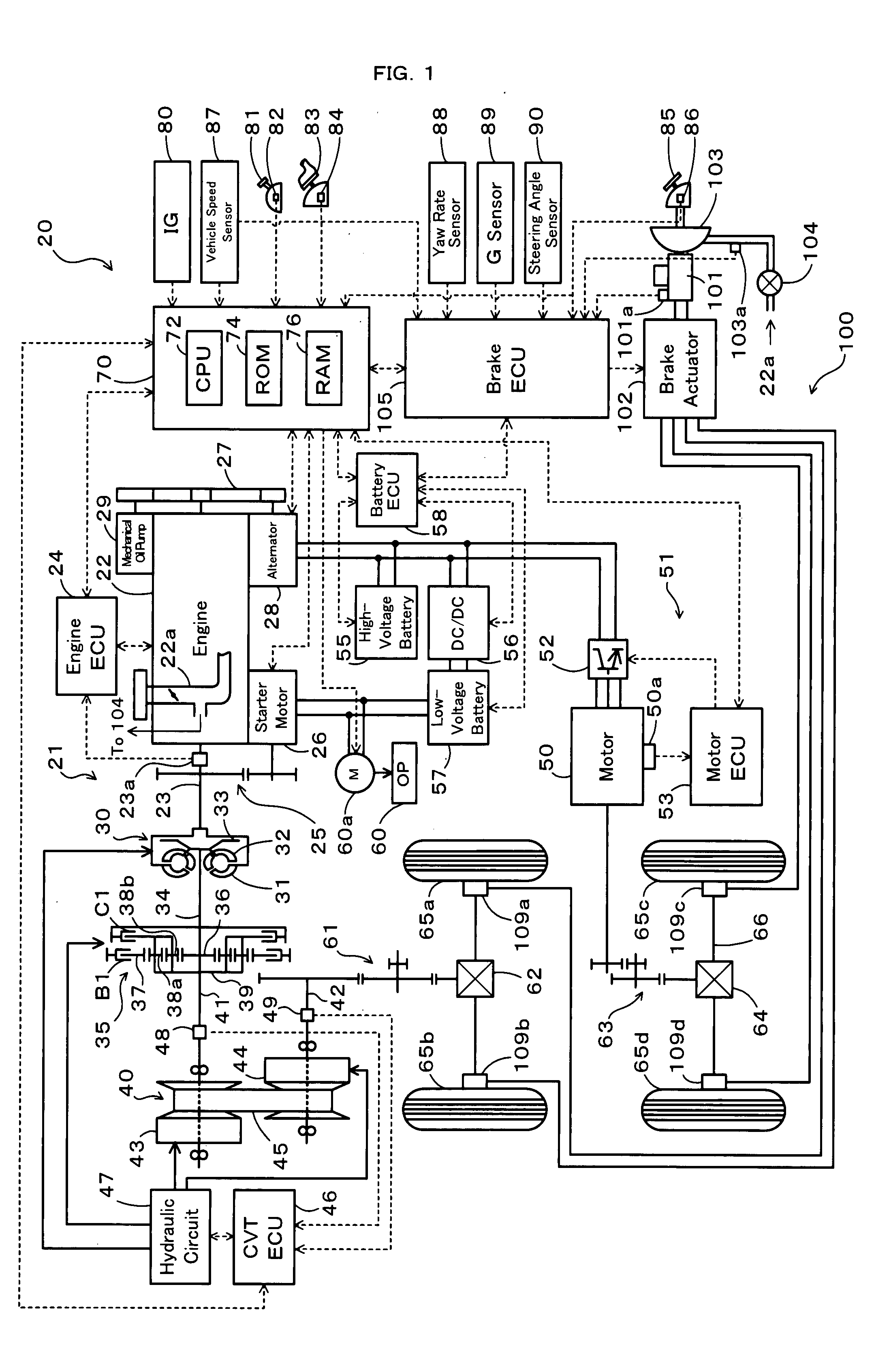
[0032]FIG. 1 schematically illustrates the configuration of a hybrid vehicle 20 in the embodiment of the invention. The hybrid vehicle 20 of the embodiment has a front wheel driving system 21 for transmission of output power of an engine 22 to front wheels 65a and 65b via a torque converter 30, a forward-backward drive switchover mechanism 35, a belt-driven continuously variable transmission (hereafter referred to as ‘CVT’) 40, a gear mechanism 61, and a differential gear 62, a rear wheel driving system 51 for transmission of output power of a motor 50 to rear wheels 65c and 65d via a gear mechanism 63, a differential gear 64, and a rear axle 66, an electronically controlled hydraulic braking system (hereafter referred to as ‘HBS’) 100 for application of braking force to the front wheels 65a and 65b and to the rear wheels 65c and 65d, and a hybrid el...


PUM


Abstract

In response to the driver's depression of a brake pedal, the hybrid vehicle of the invention utilizes both a master cylinder pressure Pmc and a pressure increase by two pumps included in two different braking systems of a brake actuator in an HBS to satisfy a braking force demand BF* required by the driver. In this case, the braking control of the invention corrects a basic pump command value dpB for the respective pumps with a pump command correction value dc (step S190), which is set according to a detected behavior of the hybrid vehicle in a braking state, and controls the brake actuator in the HBS to satisfy the braking force demand BF* (steps S170 to S200).

Description

BACKGROUND OF THE INVENTION [0001] 1. Field of the Invention [0002] The present invention relates to a vehicle and a control method of the vehicle. More specifically the invention pertains to a vehicle equipped with a fluid pressure braking system for generating a braking force, as well as to a corresponding control method of such a vehicle. [0003] 2. Description of the Prior Art [0004] In a prior art braking device for a vehicle, the proposed technique sets a front distribution and a rear distribution of a target braking force to make an ordinary gain of an actual yaw rate approach to an ordinary gain of a target yaw rate, while setting a left distribution and a right distribution of the target braking force to make the actual yaw rate approach to the target yaw rate. The braking force output from a wheel cylinder in each of left and right front and rear wheels is then regulated according to the settings of the front and rear distributions and the left and right distributions of th...

Claims


Application Information

Patent Timeline
IPC IPC(8): B60T8/64B60T8/60
CPCB60K6/48B60K6/52B60T8/1755B60T2270/613B60W10/06Y02T10/6286B60W10/184B60W20/00B60W30/18127Y02T10/6221Y02T10/6265B60W10/08Y02T10/62
Inventor KODAMA, SHINYASHIMADA, MICHIHITOMAKI, KAZUYA
Owner TOYOTA JIDOSHA KK
Why Eureka
Try Eureka