Functional element, electronic apparatus, and moving object

Active Publication Date: 2015-08-27
SEIKO EPSON CORP
View PDF4 Cites 16 Cited by
  • Summary
  • Abstract
  • Description
  • Claims
  • Application Information

AI Technical Summary

Benefits of technology

[0035]The moving object includes any of the function

Problems solved by technology

Especially when a lid (cap) for sealing the movable electrode and the support substrate are anodically bonded togethe

Method used


Image

  • Functional element, electronic apparatus, and moving object
  • Functional element, electronic apparatus, and moving object
  • Functional element, electronic apparatus, and moving object

Examples


first embodiment

1. First Embodiment

1.1. Functional Element

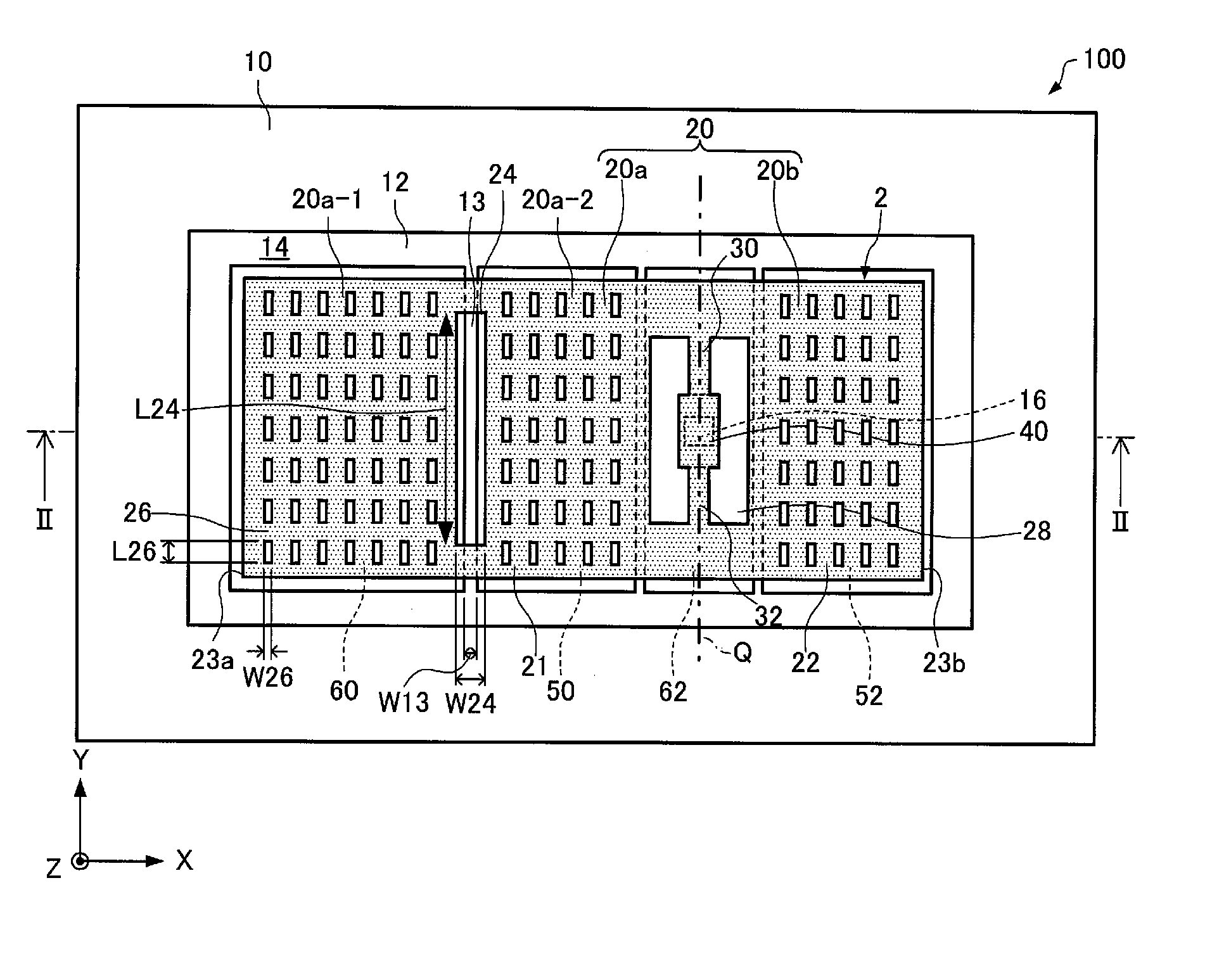
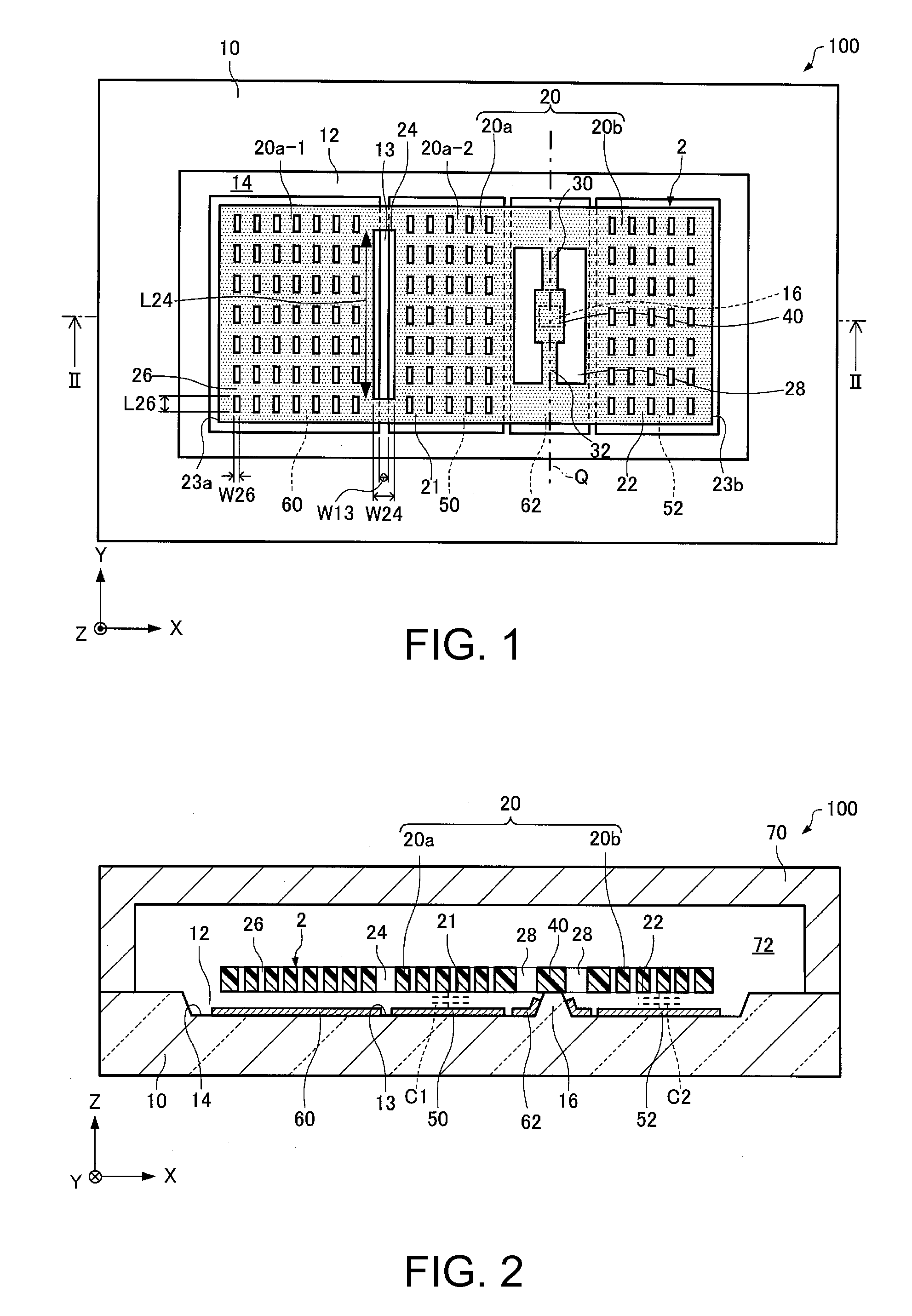
[0051]First, a functional element according to a first embodiment will be described with reference to the drawings. FIG. 1 is a plan view schematically showing a functional element 100 according to the first embodiment. FIG. 2 is a cross-sectional view taken along the line II-II in FIG. 1, schematically showing the functional element 100 according to the first embodiment. In FIGS. 1 and 2, an X-axis, a Y-axis, and a Z-axis are illustrated as three axes orthogonal to each other. Also in the drawings shown below, the X-axis, the Y-axis, and the Z-axis are illustrated similarly.

[0052]As shown in FIGS. 1 and 2, the functional element 100 includes a substrate 10, a movable body 20, support portions 30 and 32, a fixed portion 40, a first fixed electrode portion 50, a second fixed electrode portion 52, a third fixed electrode portion (hereinafter also referred to as “first dummy electrode portion”) 60, a fourth fixed electrode portion (hereinafter ...

second embodiment

2. Second Embodiment

[0123]Next, a functional element according to a second embodiment will be described with reference to the drawings. FIG. 8 is a plan view schematically showing a functional element 200 according to the second embodiment. FIG. 9 is a cross-sectional view taken along the line IX-IX in FIG. 8, schematically showing the functional element 200 according to the second embodiment. For convenience sake, the lid 70 is not illustrated in FIG. 8.

[0124]Hereinafter, in the functional element 200 according to the second embodiment, members having functions similar to those of the constituent members of the functional element 100 according to the first embodiment described above are denoted by the same reference numerals and signs, and the description thereof is omitted.

[0125]In the functional element 100 as shown in FIGS. 1 and 2, the opening 24 penetrates the movable body 20.

[0126]In contrast, in the functional element 200 as shown in FIGS. 8 and 9, the opening 24 is a recess...

third embodiment

3. Third Embodiment

[0131]Next, electronic apparatuses according to a third embodiment will be described with reference to the drawings. The electronic apparatuses according to the third embodiment each include the functional element according to the invention. Hereinafter, electronic apparatuses each including the functional element 100 as the functional element according to the invention will be described.

[0132]FIG. 10 is a perspective view schematically showing a mobile (or notebook) personal computer 1100 as an electronic apparatus according to the third embodiment.

[0133]As shown in FIG. 10, the personal computer 1100 is composed of a main body portion 1104 including a keyboard 1102, and a display unit 1106 including a display portion 1108. The display unit 1106 is rotatably supported relative to the main body portion 1104 via a hinge structure portion.

[0134]Into the personal computer 1100, the functional element 100 is built.

[0135]FIG. 11 is a perspective view schematically show...


PUM


Abstract

A functional element includes: a substrate; a movable body that includes a movable electrode portion; a support portion that supports the movable body; a first fixed electrode portion that is disposed on the substrate and a portion of which faces a first portion as one of portions of the movable body; a second fixed electrode portion that is disposed on the substrate and a portion of which faces a second portion as the other portion of the movable body; and a third fixed electrode portion that is disposed on the substrate and a portion of which faces the first portion. An opening that faces a region of the substrate between the first fixed electrode portion and the third fixed electrode portion is provided in the movable body, and the width of the opening is equal to or more than the width of the region.

Description

CROSS-REFERENCE TO RELATED APPLICATION[0001]This application claims priority to Japanese Patent Application No. 2014-034244 filed on Feb. 25, 2014. The entire disclosure of Japanese Patent Application No. 2014-034244 is hereby incorporated herein by reference.BACKGROUND[0002]1. Technical Field[0003]The present invention relates to a functional element, an electronic apparatus, and a moving object.[0004]2. Related Art[0005]In recent years, functional elements (physical quantity sensors) that detect a physical quantity such as acceleration have been developed using, for example, a silicon MEMS (Micro Electro Mechanical Systems) technique.[0006]For example, JP-A-2007-298405 discloses an electrostatic capacitive sensor including a first movable electrode and a first fixed electrode. The first movable electrode is movably supported to a fixed portion of a semiconductor layer via a beam portion so as to have an asymmetric mass balance, and operates in response to a change in physical quan...

Claims


Application Information

Patent Timeline
IPC IPC(8): G01P15/125B81B3/00
CPCB81B3/0013G01P15/125B81B3/0016G01P2015/0874
Inventor TANAKA, SATORU
Owner SEIKO EPSON CORP
Why Eureka
Try Eureka