Method for Detecting Desired Objects in a Highly Dynamic Environment by a Monitoring System

a monitoring system and dynamic environment technology, applied in the field of monitoring systems, can solve the problems of ineffective detection of foreground objects by existing automatic surveillance systems, and achieve the effect of accurate average shade or color information of pixels

Active Publication Date: 2007-11-29
AGENCY FOR SCI TECH & RES
View PDF5 Cites 85 Cited by
  • Summary
  • Abstract
  • Description
  • Claims
  • Application Information

AI Technical Summary

Benefits of technology

[0066] Therefore, the method according to this embodiment of the invention provides an additional mechanism which enables the foreground to be detected, even though the foreground object enters into an area where the pixels corresponding to the foreground object is partially obscured by large noise, such as reflection from a light source.
[0067] According to a further embodiment of the invention,

Problems solved by technology

However, when the background of the environment changes drastically or contains large dynamic noise portion, for example due to reflec

Method used


Image

  • Method for Detecting Desired Objects in a Highly Dynamic Environment by a Monitoring System
  • Method for Detecting Desired Objects in a Highly Dynamic Environment by a Monitoring System
  • Method for Detecting Desired Objects in a Highly Dynamic Environment by a Monitoring System

Examples


Embodiment Construction

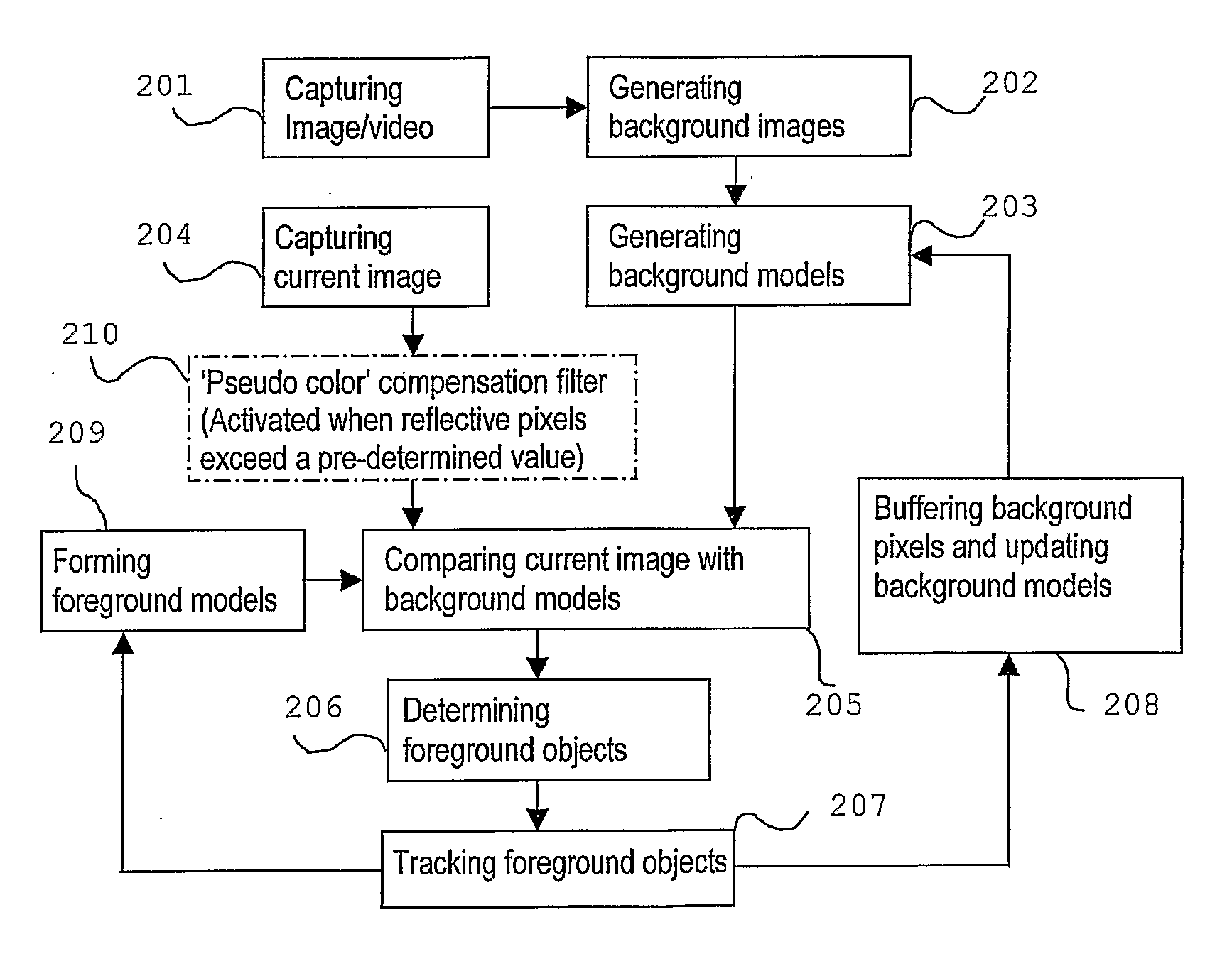
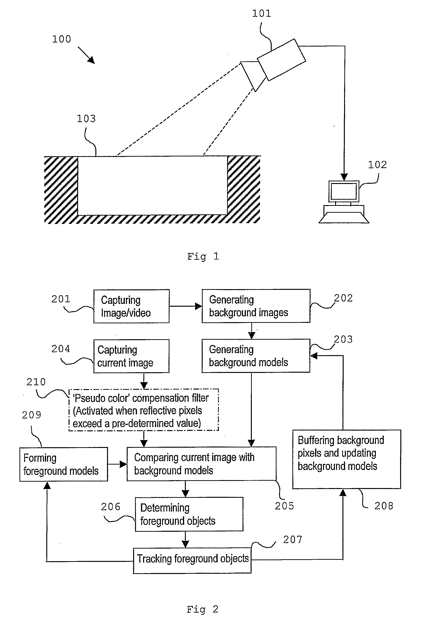
[0087]FIG. 1 shows a hardware setup of a monitoring system for monitoring a swimming pool according to an embodiment of the invention.

[0088] Although the hardware setup in FIG. 1 depicts the monitoring of a swimming pool, it should be understood that the hardware setup of the monitoring system can also be used for monitoring other kind of environment, such as inside a building.

[0089] The monitoring system 100 as shown in FIG. 1 comprises a visible light camera 101 or a video camera which is connected to a computer 102. The camera 101 is mounted at an elevated position and at an angle tilted downwards to a swimming pool 103 such that it is able at least to capture images corresponding to a portion of the swimming pool 103, and the activities therein. It is also possible to use a plurality of cameras (not shown) so that the images captured by the plurality of cameras can be combined to form the entire image of the swimming pool 103.

[0090] The images captured by the camera 101 are p...


PUM


Abstract

At least one image of the environment is taken using either an image capturing device of the monitoring system. Based on the image of the environment, at least one background image is generated. The background image, which comprises a plurality of pixels, is divided into pixel blocks. In each pixel block, at least one data cluster is formed using at least one feature of the pixels in the pixel block. The data cluster formed in each pixel block is described as a data distribution having a mean value and a standard deviation from the mean value. After generating the background image, a subsequent image is taken by the monitoring system. Each pixel of the subsequent image is compared with the data cluster of the block of the background image correspond to the pixel, and a first discrepancy value is generated accordingly. The pixel of the subsequent image is further compared with the data distribution of at least another pixel block which is adjacent to the pixel block of the background image corresponding to the pixel, and a second discrepancy value is generated as a result of this comparison. Based on the first and second discrepancy value, the pixel of the subsequent image is determined to be either a background pixel or a foreground pixel. After all the pixels in the subsequent image have been determined as either a background or a foreground pixel, a binary map is generated. The connected foreground pixels in the binary map are marked to form a foreground object, which is the detected objected in the environment according to the invention.

Description

BACKGROUND OF THE INVENTION [0001] The invention relates to a monitoring system and a method for detecting at least one object in an environment by the monitoring system. [0002] A surveillance system is commonly installed in places such as homes, offices and other public areas to monitor activities occurring in these environments. In the surveillance system, cameras, video cameras or other sensing devices are often used to capture images or videos of the environments, and usually an operator (a person) analyzes the captured images or videos to understand and monitor the activities occurring in the environments. [0003] For example, a surveillance system may be installed in a building to monitor the presence of intruders in the building. In another example, a surveillance system may be installed to monitor the activities of a swimming pool. The real-time images or videos of the swimming pool provided by the surveillance system may be monitored by a person who, upon detecting any possi...

Claims


Application Information

Patent Timeline
IPC IPC(8): H04N7/18G06T7/20G06V10/28
CPCG06K9/00771G06T7/2053G06K9/38G06T7/254G06V20/52G06V10/28
Inventor WANG, JUNXIANENG, HOW LUNGKAM, SIEW WAH ALVIN HARVEYYAU, WEI YUN
Owner AGENCY FOR SCI TECH & RES
Why Eureka
Try Eureka