X-ray ct apparatus

a technology of x-ray and ct, applied in the field of x-ray computer tomography (ct) apparatus, can solve the problems of deteriorating the quality of reproduced images based on incorrect data, becoming a serious problem for image diagnosis apparatus, and adding weight, so as to reduce the distortion of the rotation frame, increase the weight of the x-ray ct apparatus, and reduce the distortion

Inactive Publication Date: 2007-11-29
TOSHIBA MEDICAL SYST CORP
View PDF2 Cites 11 Cited by
  • Summary
  • Abstract
  • Description
  • Claims
  • Application Information

AI Technical Summary

Benefits of technology

[0014] The present invention addresses the problems and defects of the conventional apparatus and provides a new X-ray CT apparatus that can constrain distortions of a rotation frame due to high speed rotation in order to avoid occurrence of displacements of an X-ray source and an X-ray detector that are provided on the rotation frame. Consequently, the X-ray CT apparatus according to the present invention can achieve a high efficiency of diagnosis without increasing the weight of the X-ray CT apparatus.
[0016] As thus configured, there is provided a novel X-ray CT apparatus that can achieve high speed rotation of a rotation frame for supporting an X-ray source (X-ray tube) and an X-ray detector while preventing distortions of the rotation frame from occurring during high speed rotation. Thus, the X-ray CT apparatus of the present invention can prevent displacements of the X-ray source and the X-ray detector from occurring during a high speed rotation of the rotation frame. It is also possible for the X-ray CT apparatus of the present invention to increase observation efficiencies while being kept light weight.
[0029] According to a further aspect of the X-ray CT apparatus of the present invention, even when a rotation frame receives a large centrifugal acceleration during a high speed rotation, the rigidity of the fixed frame and the plurality of bearing units provided between the fixed frame and the rotation frame can prevent the rotation frame from expanding to outer sides. Accordingly, it becomes possible to prevent an X-ray tube and an X-ray detector on the rotation frame from displacing at predetermined positions. Consequently, deterioration of reconstructed images can be prevented.
[0030] According to a further aspect of the X-ray CT apparatus of the present invention, even when the rotation frame is rotated at a higher speed and the rotation frame receives much larger centrifugal accelerations, pitching vibrations of the rotation frame can be prevented from occurring, since the rigidities along a forward and backward directions of the rotation frame are increased. Consequently, occurrences of displacements of relative positions of the X-ray tube and the X-ray detector can be reduced when the rotation frame rotates in a high speed. Thus, deterioration of reconstructed images can be prevented.

Problems solved by technology

Such displacements of X-ray tube 20 and X-ray detector 30 due to a high speed rotation of the rotation frame 10 generate errors in the acquired image data through the detector and deteriorate the quality of reproduced images based on incorrect data.
It may become a serious problem for an image diagnosis apparatus.
However, such a construction adds weight and makes the apparatus complicated and heavy.
Consequently, an X-ray CT apparatus becomes much larger and heavier as a whole when measures are taken to strengthen the bearing units and the rotation frame.

Method used


Image

  • X-ray ct apparatus
  • X-ray ct apparatus
  • X-ray ct apparatus

Examples


Embodiment Construction

[0044] Referring now to FIGS. 1-8, embodiments of the present invention will be explained. As an exemplary embodiment according to the present invention, a helical scan X-ray CT apparatus will be described. Of course, the present invention is applicable to any type of X-ray CT apparatus.

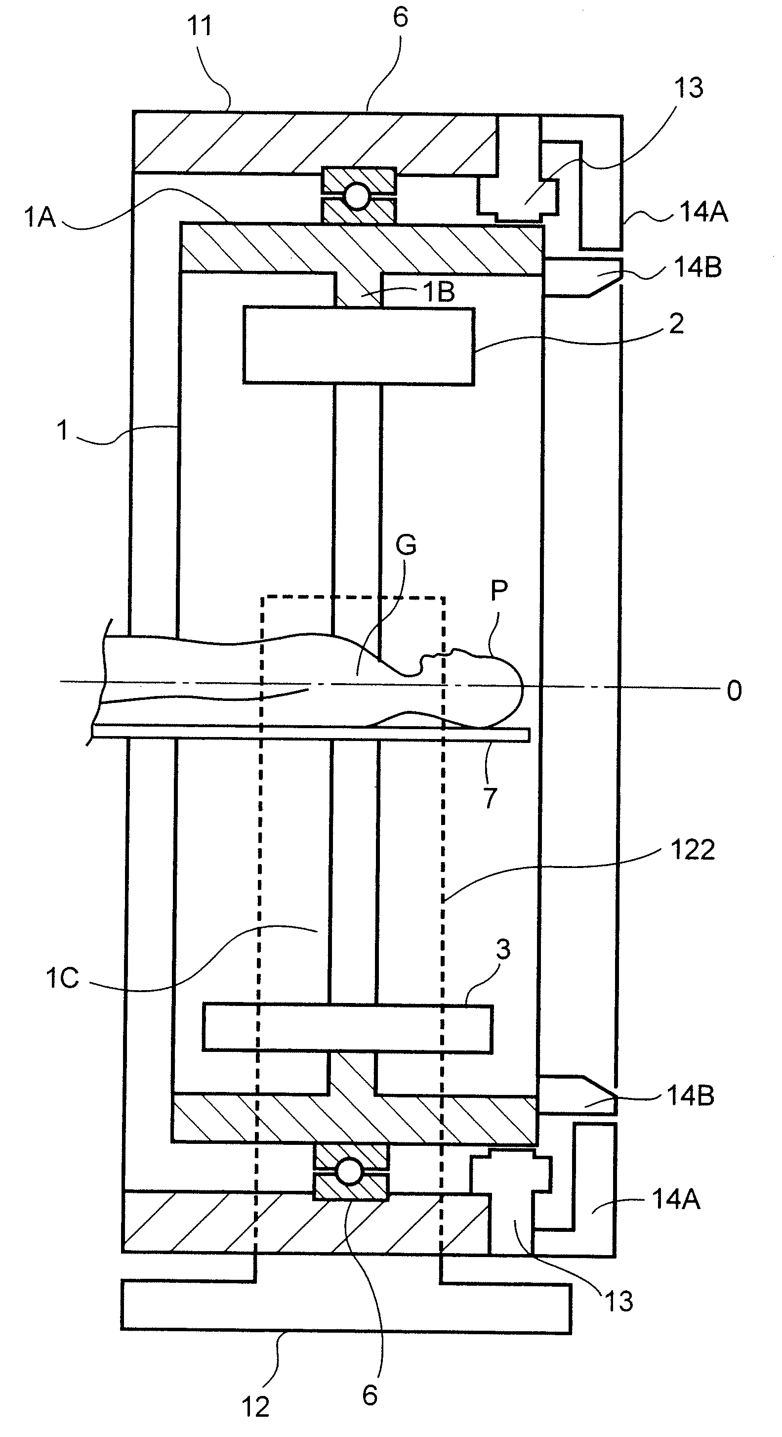
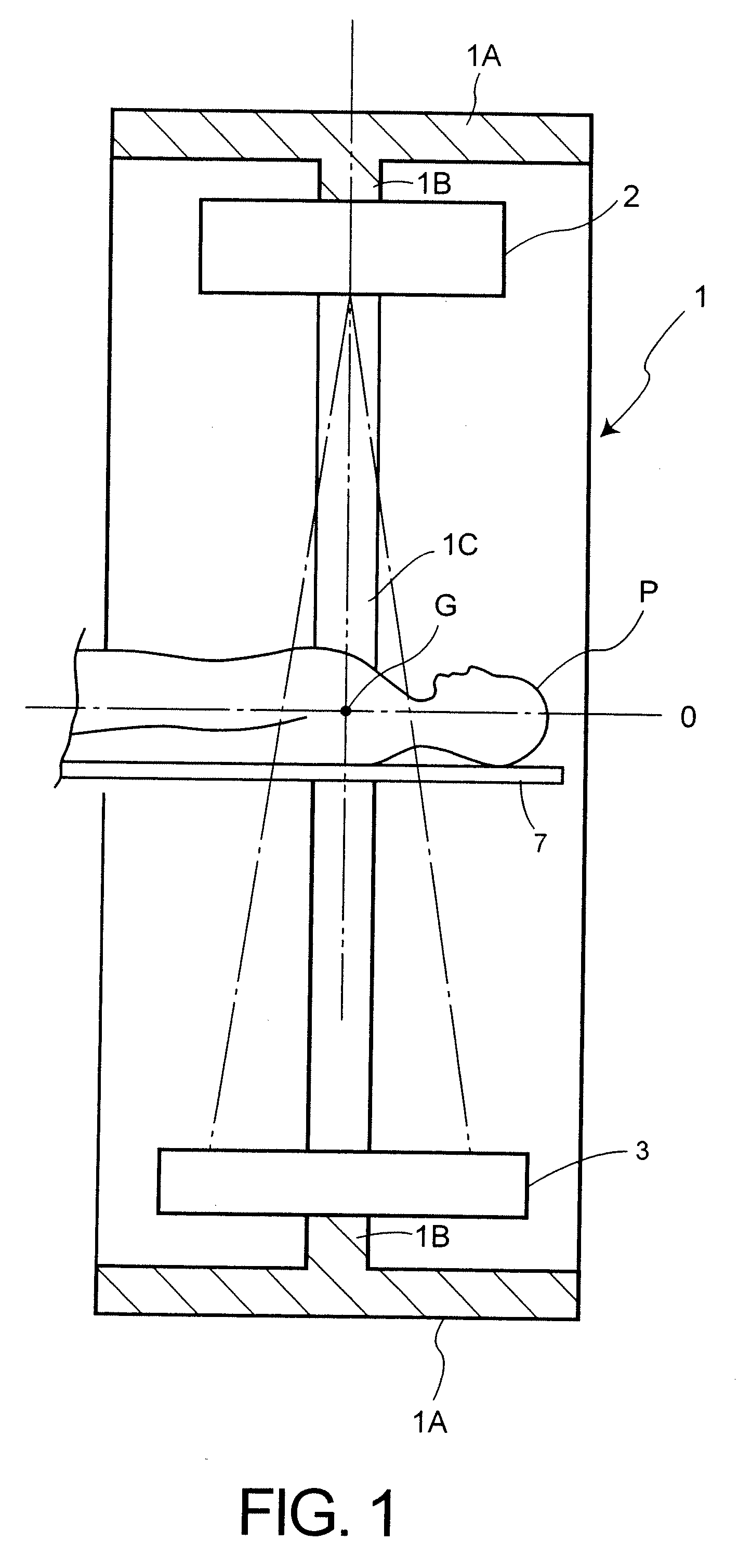
[0045]FIG. 1 is a cross-section view of a drum type rotation frame of an X-ray CT apparatus consistent with the present invention. As shown in FIG. 1, a drum type rotation frame 1 includes an annulus ring member 1A surrounding a rotation axis 0 of the drum type rotation frame 1 and a circular rib member 1B that is projected from an inner surface of the annulus ring member 1A along a hypothetical line Y that orthogonally crosses the rotation axis O at a substantial center of the annulus ring member 1A and passes through a center of gravity G of the rotation frame. For instance, the annulus ring member 1A and the circular rib member 1B are made as a unitary body by an aluminium (Al) casting. Of course...


PUM

PropertyMeasurementUnit
angleaaaaaaaaaa
revolution radiusaaaaaaaaaa
rotation radiusaaaaaaaaaa

Abstract

An X-ray CT apparatus, wherein a drum type rotation frame is rotatably supported by a fixed circular frame so as to surround an outer surface of the drum type rotation frame through a plurality of bearings provided between an inner surface of the fixing circular frame and an outer surface of the drum type rotation frame, for example in ring-like configuration. When the drum type rotation frame receives a large centrifugal acceleration due to a high speed rotation, outside expansion of the drum type rotation frame can be constrained due to both the rigidity of the fixed frame and the rigidity of the plurality of bearings provided on the outer surface of the rotation frame, thereby to maintain the relative positions of the X-ray tube and the X-ray detector and prevent deterioration of reconstructed images.

Description

CROSS-REFERENCE TO RELATED APPLICATIONS [0001] This application claims priority from, and the benefit of, Japanese Patent Application No. 2006-133817, filed on May 12, 2006, the contents of which are expressly incorporated herein by reference in their entirety. BACKGROUND OF THE INVENTION [0002] 1. Field of the Invention [0003] The present invention relates to an X-ray computer tomography (CT) apparatus, and particularly, to an X-ray CT apparatus that can prevent displacements of an X-ray source and an X-ray detector that are mounted on a rotation frame provided in a gantry of the X-ray CT apparatus when the rotation frame rotates at high speed. [0004] 2. Discussion of the Background [0005] Usually, an X-ray CT apparatus includes, as illustrated in FIG. 8, an X-ray tube 20 and an X-ray detector 30 provided on a vertical circle member of a rotation frame 10 in a gantry so as to face each other through a center aperture 10C of the gantry. An object P is inserted into the center apertu...

Claims


Application Information

Patent Timeline
Patent Type & Authority Applications(United States)
IPC IPC(8): A61B6/00G01N23/00G21K1/12H05G1/60
CPCA61B6/4488A61B6/035
Inventor HARADA, TOMOKAZUNAKANO, MAKOTOSADOTOMO, TETSUYASHINDO, YASUTAKAGOTANDA, KATSUMI
Owner TOSHIBA MEDICAL SYST CORP
Why Eureka
Try Eureka