Connector assembly

Active Publication Date: 2007-11-29
ADVANCED CONNECTEK INC
View PDF5 Cites 21 Cited by
  • Summary
  • Abstract
  • Description
  • Claims
  • Application Information

AI Technical Summary

Benefits of technology

[0009]A connector assembly in accordance with the present invention comprises a plug connector and a socket connector. The plug connector has a first insulative housing and at least one row of first terminals. The first terminals are mounted on the first insulative housing and each terminal has an inside contacting portion and an interference portion. The socket connector has a second insulative housing and at least one row of second terminals corresponding respectively to the at le

Problems solved by technology

Therefore, the plug connector would be engaged loosely with and easily disengages inadvertently from the socke

Method used


Image

  • Connector assembly
  • Connector assembly
  • Connector assembly

Examples


Embodiment Construction

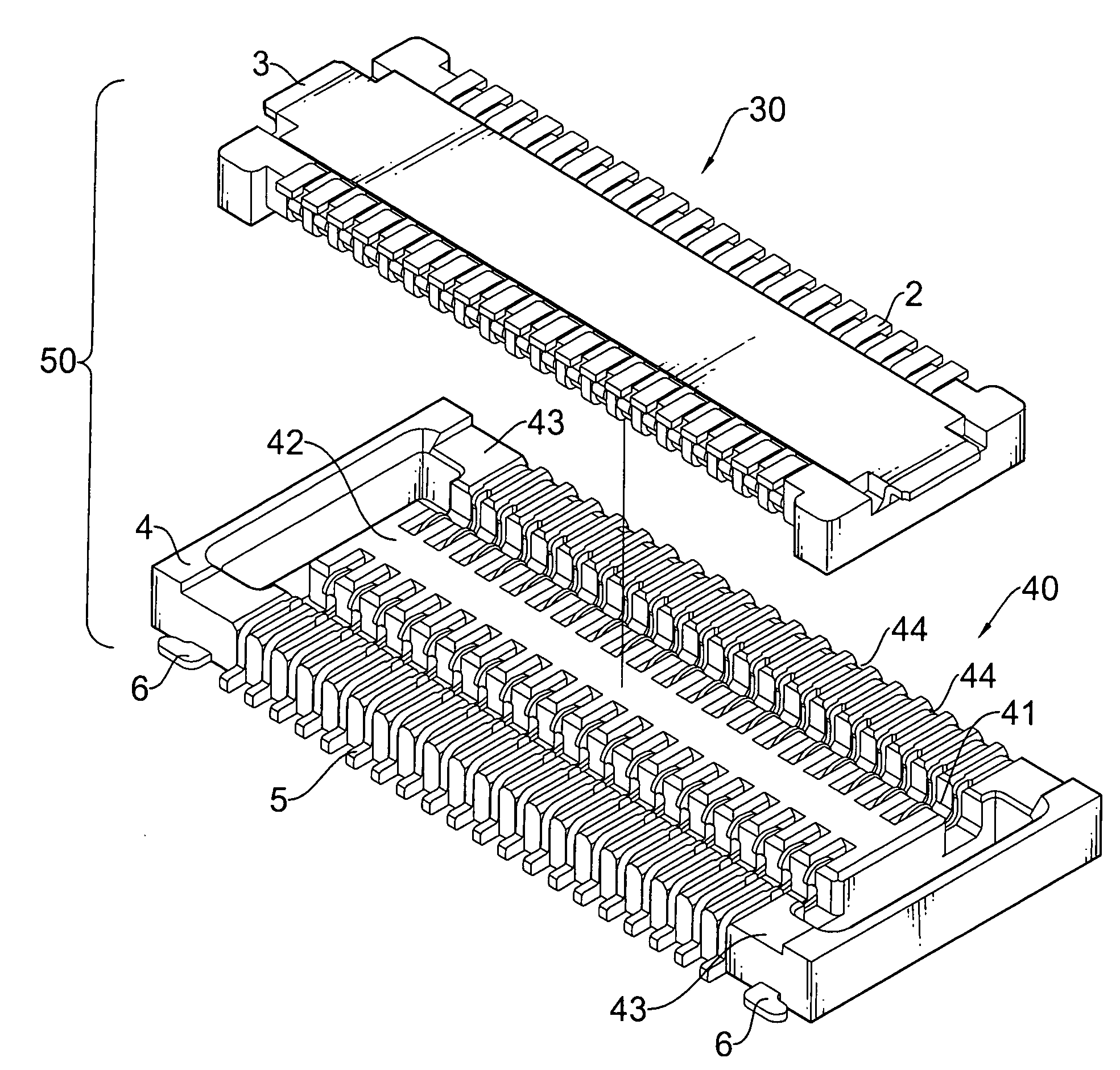
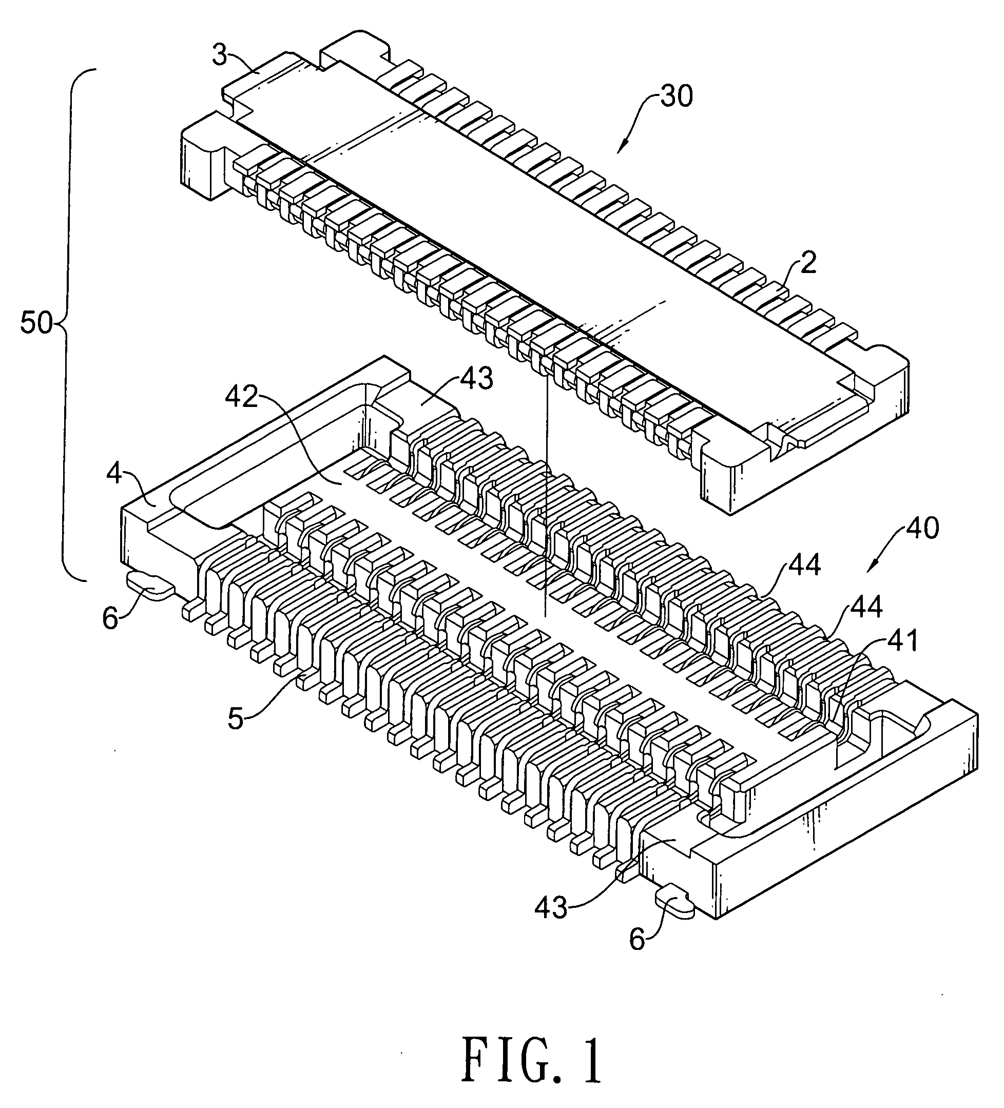
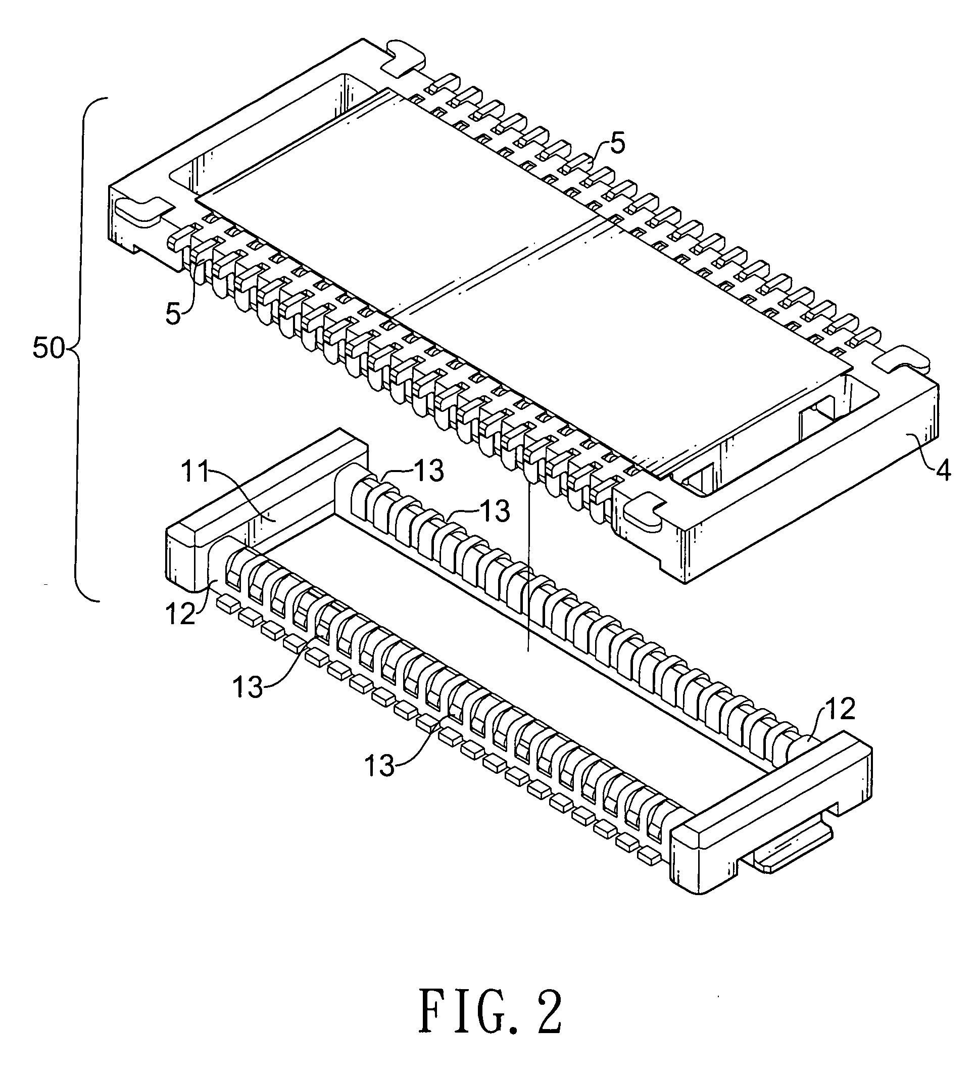
[0020]With reference to FIGS. 1 and 2, a first embodiment of a connector assembly 50 in accordance with the present invention is mounted between two printed circuit boards and comprises a plug connector 30 and a socket connector

[0021]The plug connector 30 has a first insulative housing 1, two rows of first terminals 2 and two ground contacts 3.

[0022]The first insulative housing 1 has two ends, two opposite sides 12, a cavity 11 and two rows of mounting recesses 13. The cavity 11 is defined in the first insulative housing 1. The mounting recesses 13 of each row are defined in one of the side 13 and each mounting recess 13 has an inner surface 131.

[0023]With reference to FIGS. 3 and 4, the rows of the first terminals 2 correspond respectively to the sides 12 and the first terminals 2 of each row are mounted respectively in the mounting recesses 13 in a corresponding side 13 adjacent to the inner surface 131. Each first terminal 2 is formed from an L-shaped semi-finished first terminal...


PUM


Abstract

A connector assembly has a plug connector and a socket connector. The plug connector has a first insulative housing and at least one row of first terminals. The first terminals are mounted on the first insulative housing and each terminal has an inside contacting portion and an interference portion. The socket connector has a second insulative housing and at least one row of second terminals corresponding respectively to the at least one row of the first terminals. The second terminals are selectively engaged and respectively with the first terminals and each second terminal has an inner contacting portion and a shoulder portion. The inner contacting portion selectively contacts the inside contacting portion of one first terminal. The shoulder portion is selectively engaged with the interference portion of one first terminal and prevents the first terminal from disengaging inadvertently from the second terminal.

Description

BACKGROUND OF THE INVENTION[0001]1. Field of the Invention[0002]The present invention relates to a connector assembly, and more particularly to a connector assembly that has a plug connector and a socket connector may be engaged securely with the plug connector.[0003]2. Description of Related Art[0004]Signal transmission between two printed circuit boards (PCBs) are implemented generally through a connector assembly having a plug connector on one PCB and a socket connector on the other PCB.[0005]With reference to FIG. 9, a conventional connector 100 in accordance with the prior art comprises a plug connector 10 and a socket connector 20. The plug connector 10 has a row of first terminals. The socket connector 20 has a row of second terminals selectively contacting the row of the first terminal.[0006]However, each first terminal contacts a corresponding second terminal merely in one single point without any locking structures. Therefore, the plug connector would be engaged loosely wi...

Claims


Application Information

Patent Timeline
IPC IPC(8): H01R12/00
CPCH01R13/41H01R13/415H01R12/73H01R12/716H01R12/52H01R13/20
Inventor WANG, MEI-HUI
Owner ADVANCED CONNECTEK INC
Why Eureka
Try Eureka