Integrated control circuit for an oxygen mask

a control circuit and oxygen mask technology, applied in breathing masks, breathing protection, flying suits, etc., can solve problems such as limiting the ability of users to utilize the same on both sides

Active Publication Date: 2007-12-06
GENTEX CORP
View PDF30 Cites 16 Cited by
  • Summary
  • Abstract
  • Description
  • Claims
  • Application Information

AI Technical Summary

Benefits of technology

[0013]A housing enclosing the electrical connection block is mounted to an exterior of the rigid portion, with a window formed therein for emitting night vision compatible light in response to the integrated control circuit. The integrated control circuit allows a user to activate the light, in a hands-free manner, that avoids interference with a night vision device. At least a portion of said housing is coated with an EMI-shielding, conductive, stable nickel acrylic lacquer. The window may include a spectrally select filter. Behind the window, a light emitting source is mounted onto the electrical connection block for emitting light through the spectrally select filter to produce night vision compatible illumination in a tracking relationship to the oxygen mask and therefore the user's head and eyes. The housing and window are configured and designed to contain the electrical connection block and said light source during ejection in order to protect the wearer from flying debris.

Problems solved by technology

However, such aircraft lighting means are described for applications concerning instrument panel lighting systems, light scattering devices for ambient light in pilot's cockpits, light indicators, luminous graphics display systems, position or navigation lights, landing lights, flight training lights, anti-collision lights, etc., but not with respect to integrating the same with a user's helmet and, further, not with respect to integrating the same with respect to a respiratory sub-system.
However, the head mounted illumination device is not disclosed with respect to integrating the same with a user's helmet and, further, not with respect to integrating the same with respect to a respiratory sub-system.
However, the cockpit blackout search and survival light is not disclosed with respect to mounting in a central position to readily allow for the provision of light on either side of the user, thus limiting the ability of the user to utilize the same on both sides thereof, a very necessary function in a dark or darkened cockpit environment.
However, the aircraft application appears to relate to aircraft that do not use or require respiratory sub-systems such as, e.g., helicopters and, thus, the helmet mounted aviation night vision illuminating device is not disclosed with respect to integrating the same with respect to a respiratory sub-system.

Method used


Image

  • Integrated control circuit for an oxygen mask
  • Integrated control circuit for an oxygen mask
  • Integrated control circuit for an oxygen mask

Examples


Embodiment Construction

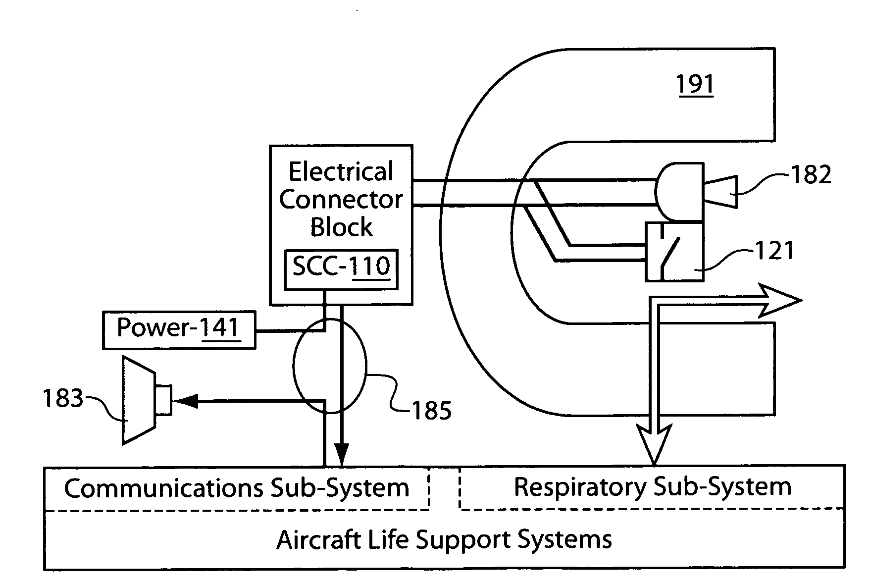
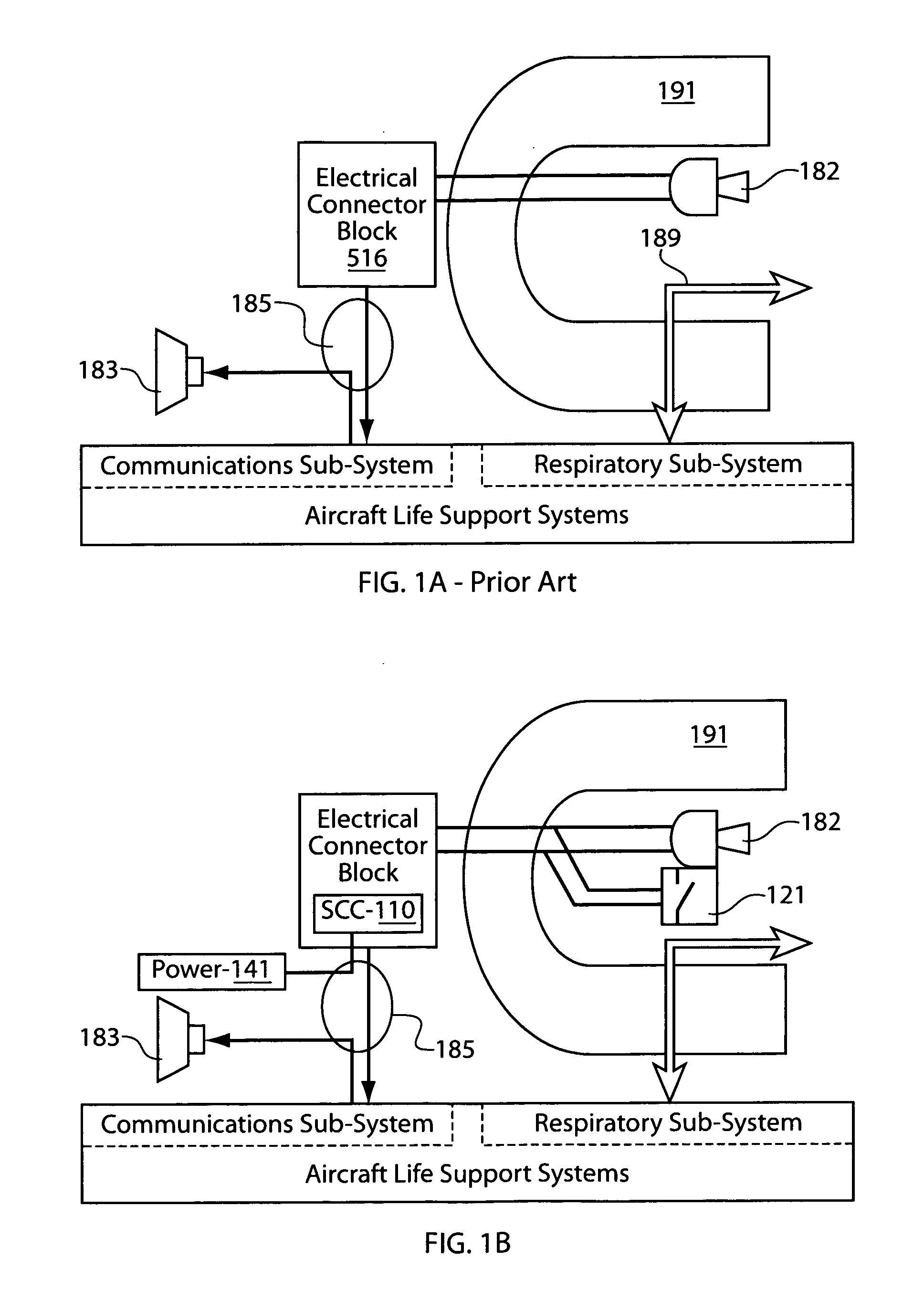
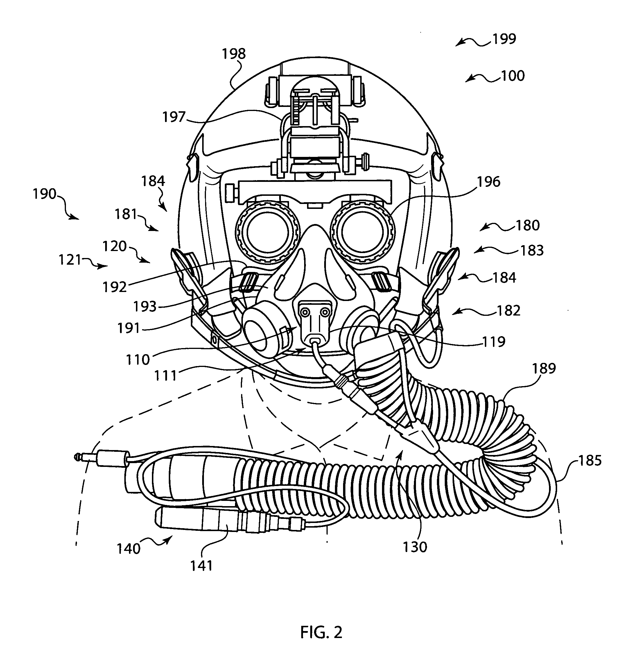
[0027]The present invention is directed to an integrated control circuit to selectively activate an aviation mask light in a hands-free manner for use with an aviation life support system, and particularly for use in conjunction with a night vision system.

[0028]The present description illustrates the principles of the present invention. It will thus be appreciated that those skilled in the art will be able to devise various arrangements that, although not explicitly described or shown herein, embody the principles of the invention and are included within its spirit and scope.

[0029]All examples and conditional language recited herein are intended for pedagogical purposes to aid the reader in understanding the principles of the invention and the concepts contributed by the inventor to furthering the art, and are to be construed as being without limitation to such specifically recited examples and conditions.

[0030]Moreover, all statements herein reciting principles, aspects, and embodi...


PUM


Abstract

A safety device integrated into a respiratory system that includes an oxygen mask having a cup-shaped rigid portion overlying a face mating portion to define a respiratory envelope that is adapted to sealingly engage over the mouth and nose of a user. An integrated control circuit includes an externally mounted connection block and a circuit looping through the respiratory envelope. A hands-free, mouth-activated switch is located within the cup-shaped rigid portion and is electrically coupled to the control circuit.

Description

FIELD OF THE INVENTION[0001]The present invention relates generally to aviation life support systems and, more particularly, to a control circuit integrated into an oxygen mask.BACKGROUND OF THE INVENTION[0002]Typical aviation life support systems for non-rotary aircraft provide a communications sub-system and a respiration sub-system. Such communications sub-systems include a microphone and a speaker, to allow a user to communicate with an entity remote from the aircraft. Moreover, such respiration sub-systems include an oxygen mask for providing the user with fresh air or oxygen while expelling CO2.[0003]U.S. Pat. No. 6,758,586 discloses an aircraft lighting means compatible with a night vision imaging system. However, such aircraft lighting means are described for applications concerning instrument panel lighting systems, light scattering devices for ambient light in pilot's cockpits, light indicators, luminous graphics display systems, position or navigation lights, landing ligh...

Claims


Application Information

Patent Timeline
Patent Type & Authority Applications(United States)
IPC IPC(8): A62B7/00A62B18/08
CPCB64D10/00A62B18/08
Inventor OSBORNE, ANTHONYMCCAY, ROBERT
Owner GENTEX CORP
Why Eureka
Try Eureka