Lighting device with color control, and method of lighting

a technology of light source and color control, applied in the direction of electric variable regulation, process and machine control, instruments, etc., can solve the problems of incandescent light bulbs, fluorescent light bulbs, and still less efficient as compared to solid-state light emitters, such as light emitting diodes

Active Publication Date: 2007-12-06
IDEAL IND LIGHTING LLC
View PDF68 Cites 159 Cited by
  • Summary
  • Abstract
  • Description
  • Claims
  • Application Information

AI Technical Summary

Benefits of technology

[0027] The present invention is directed to such devices and methods, i.e., to devices and methods by which the color (e.g., the color temperature of white light) and/or output luminance (or intensity) of light em

Problems solved by technology

It is well-known that incandescent light bulbs are very energy-inefficient light sources—about ninety percent of the electricity they consume is released as heat rather than light.
Fluorescent light bulbs are more efficient than incandescent light bulbs (by a factor of about 10) but are still less efficient as compared to solid state light emitters, such as light emitting diodes.
In addition, as compared to the normal lifetimes of solid state light emitters, e.g., light emitting diodes, incandescent light bulbs have relatively short lifetimes, i.e., typically about 750-1000 hours.
Fluorescent bulbs have longer lifetimes (e.g., 10,000-20,000 hours) than incandescent lights, but provide less favorable color reproduction.
Another issue faced by conventional light fixtures is the need to periodically replace the lighting devices (e.g., light bulbs, etc.).
Such issues are particularly pronounced where access is difficult (e.g., vaulted ceilings, bridges, high buildings, traffic

Method used


Image

  • Lighting device with color control, and method of lighting
  • Lighting device with color control, and method of lighting
  • Lighting device with color control, and method of lighting

Examples


first embodiment

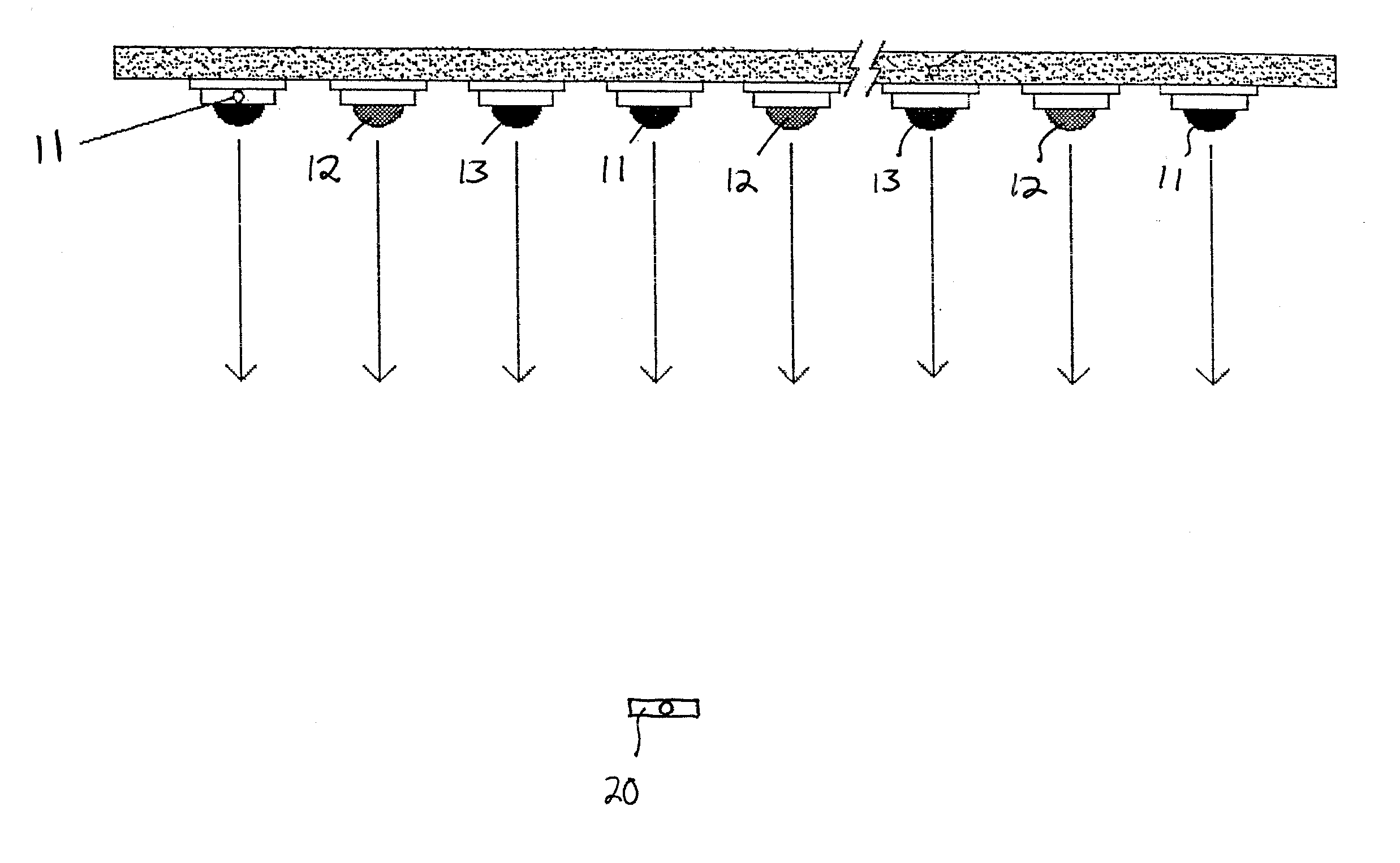
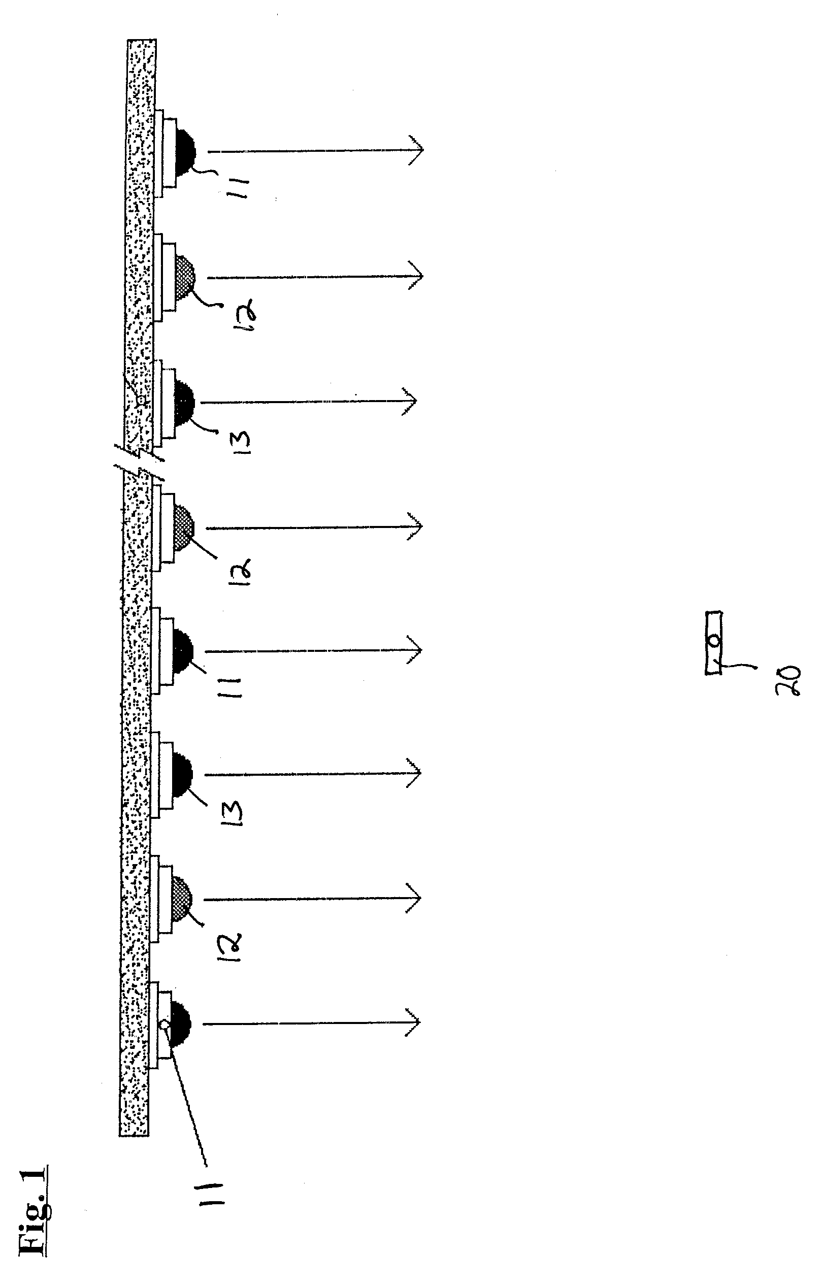
[0094]FIG. 1 depicts a lighting device 10 according to the present invention. Referring to FIG. 1, the lighting device 10 includes a plurality of first group solid state light emitters 11 (LEDs of a first dominant wavelength), a plurality of second group solid state light emitters 12 (LEDs of a second dominant wavelength) and a plurality of third group solid state light emitters 13 (LEDs of a third dominant wavelength). The lighting device 10 further includes a first reference sensor 20.

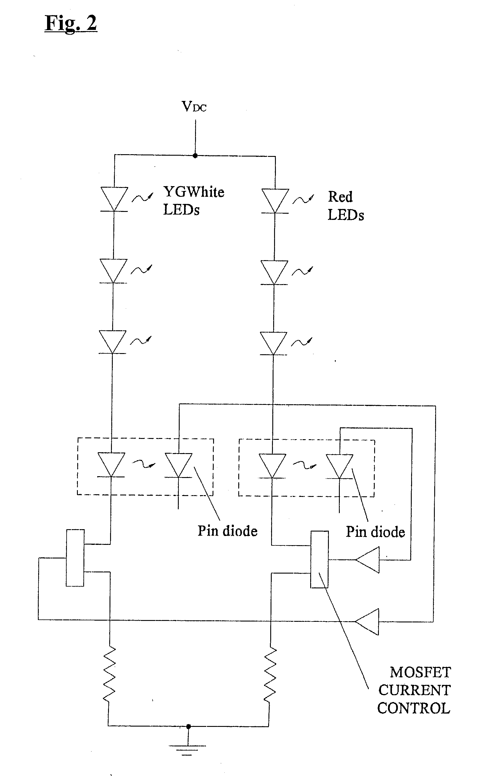
[0095]FIG. 2 is an electrical schematic diagram of a first embodiment according to the present invention.

second embodiment

[0096]FIG. 3 is an electrical schematic diagram of a second embodiment according to the present invention.

[0097] Any two or more structural parts of the lighting devices described herein can be integrated. Any structural part of the lighting devices described herein can be provided in two or more parts (which are held together, if necessary). Similarly, any two or more functions can be conducted simultaneously, and / or any function can be conducted in a series of steps.


PUM


Abstract

A lighting device comprising a group of one of more illumination solid state light emitters, a reference solid state light emitter and a reference sensor which detects an intensity of the reference solid state light emitter. Each of the emitters (1) has an illumination which is spaced from a first point by a delta u′, v′ distance on a 1976 CIR diagram of not more than 0.015, and/or (2) has a forward voltage temperature dependence which is within 5% of a first forward voltage temperature dependence. In addition, a lighting device comprising one or more illumination solid state light emitters, a reference solid state light emitter and a sensor which comprises at least two areas of individual sensors. Also, methods of lighting.

Description

CROSS-REFERENCE TO RELATED APPLICATIONS [0001] This application claims the benefit of U.S. Provisional Patent Application No. 60 / 809,461, filed May 31, 2006, the entirety of which is incorporated herein by reference.FIELD OF THE INVENTION [0002] The present invention is directed to a lighting device, more particularly, a lighting device which maintains and / or adjusts the color of light output and the intensity of the light output. In particular, the invention relates to providing such color control in lighting devices which comprise one or more solid state light emitters. The present invention is also directed to a method of lighting which provides color control in lighting devices which comprise one or mote solid state light emitters. BACKGROUND OF THE INVENTION [0003] A large proportion (some estimates are as high as twenty-five percent) of the electricity generated in the United States each year goes to lighting. Accordingly, there is an ongoing need to provide lighting which is ...

Claims


Application Information

Patent Timeline
IPC IPC(8): H05B39/00H05B41/00H05B37/00H05B44/00
CPCH05B33/0869Y02B20/341H05B33/0872H05B45/20H05B45/22Y02B20/30H05B45/28H05B41/00
Inventor VAN DE VEN, ANTONY PAUL
Owner IDEAL IND LIGHTING LLC
Why Eureka
Try Eureka