Through-hull light

a technology of through-hull lights and light fixtures, which is applied in the direction of lighting devices, light fastenings, lighting apparatus, etc., can solve the problems of inability to permanently attach underwater lights to the exterior of the hull, inability to optimize the angle of incidence and sweep of beam patters, and laborious and cumbersome to lower lights on lines and cables from the deck of the vessel

Inactive Publication Date: 2007-12-06
URQUHART PETER
View PDF33 Cites 19 Cited by
  • Summary
  • Abstract
  • Description
  • Claims
  • Application Information

AI Technical Summary

Benefits of technology

[0014]The foregoing objects and features of the invention will be more readily understood from a consideration of the following detailed description, taken with the accompanying drawings, in which corresponding parts are indicated by corresponding numerals.

Problems solved by technology

However, in many cases a greater degree of illumination beneath the water surface is desired which can only be achieved if the light source is underwater.
It is not practical to permanently attach underwater lights to the exterior of the hull due to the excessive drag that would be created, not to mention the severe mechanical strains on such appendages at high velocities of vessel travel.
It is also tedious and cumbersome to lower lights on lines and cables from the deck of the vessel.
Numerous problems have been encountered with prior art thru-hull lights that have heretofore been commercialized for use with surface vessels, among them the problem of angle of incidence and sweep of their beam patters not being optimized.
Also, it is not possible to optimize the illumination of the water near a marine vessel in which an underwater thru-hull light is mounted for all boat types as the orientation of the vessel hull, e.g. transom, relative to vertical and horizontal planes varies significantly among vessel-types.
However, the reflector is not adjustable from within the vessel, rendering adjustment thereof extremely difficult, as adjustment of the orientation of the reflector can only be performed by a person situated in or upon the water, exterior of the vessel.
Also, providing means for adjusting the orientation of a submerged or submersible light risks breaching whatever watertight seal is associated with the light.

Method used


Image

  • Through-hull light
  • Through-hull light
  • Through-hull light

Examples


Embodiment Construction

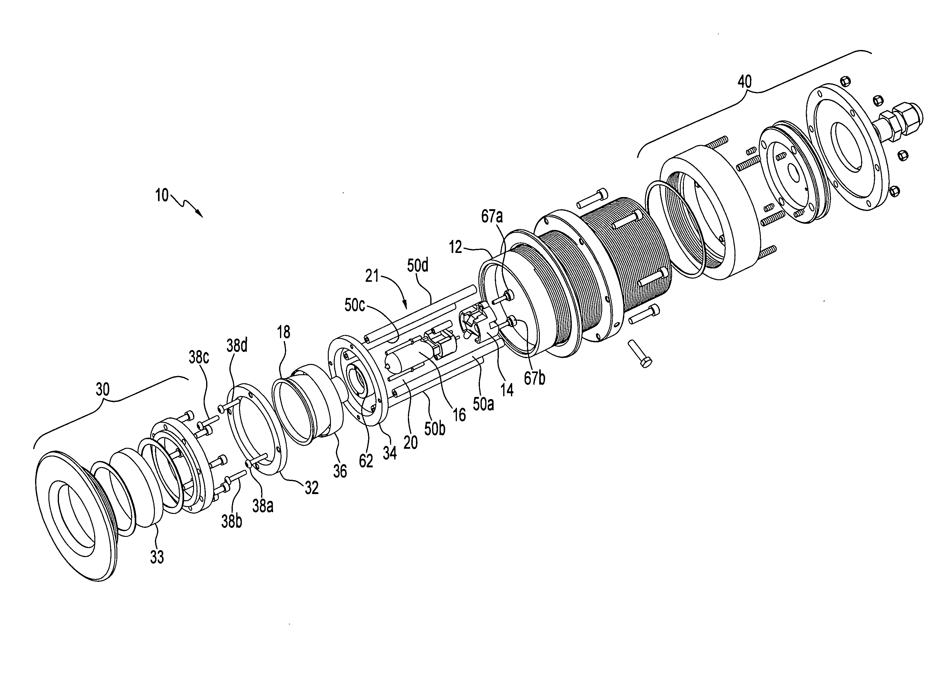
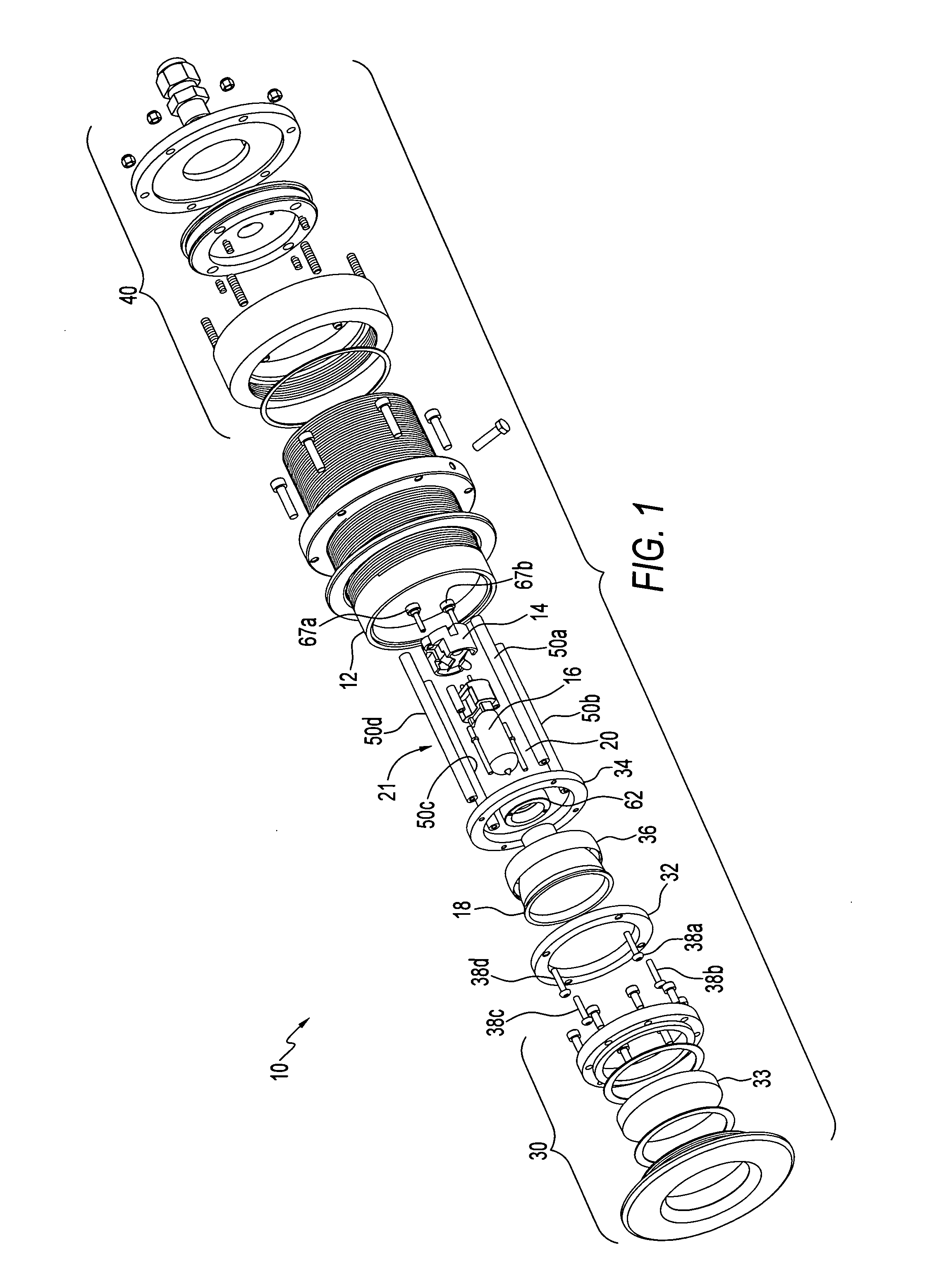
[0026]Referring now to the drawings, FIG. 1 shows, in exploded perspective, the preferred embodiment of the illumination device 10 of the invention which is comprised of a cylindrical housing or body member 12 surrounding a lamp bulb or lamp socket 14, a bulb or lamp fixture 16, spherical ring (36), a reflector 18, a first linear lamp adjustment apparatus 20, and a second, angular lamp adjustment structure 21, which will be described in more detail below.

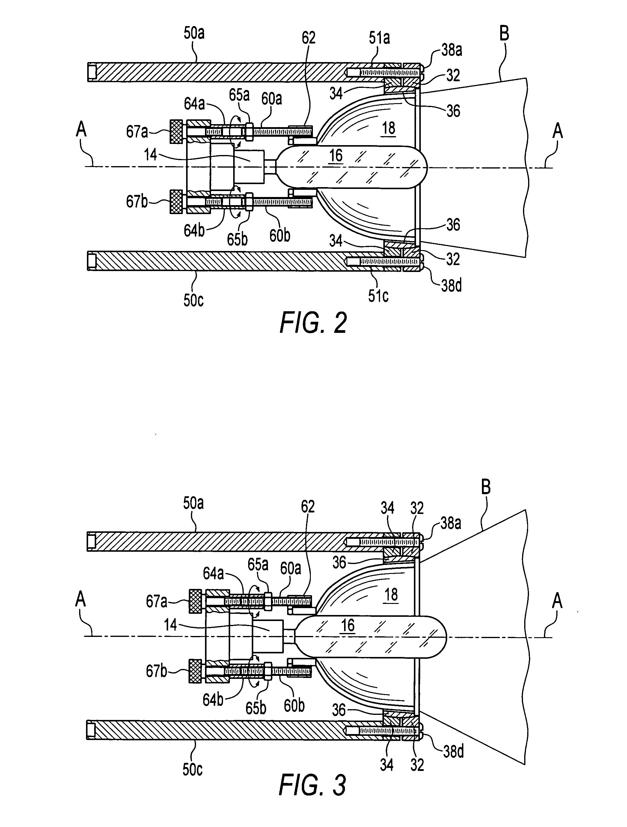
[0027]A front end closure assembly 30 is employed, which preferably includes a transparent lens 33 and which may be of any suitable configuration. Likewise, a rear removable closure assembly 40 is employed to cover the rear end of device 10. As seen in FIGS. 2 and 3, lamp 16 resides in substantially coaxial orientation relative to reflector 18, and is movable along axis A between a fully extended position (not shown) and a retracted position (shown in FIG. 3). FIG. 3 shows bulb 16 in a partially extended position. When bulb 16 is in...


PUM


Abstract

An illumination apparatus which is, in the preferred embodiment, adapted to be mounted in a through-hull configuration in a marine vessel, and which is comprised of a housing, which is preferably cylindrically shaped, surrounding a light bulb and light bulb socket, or terminal block, a reflector, first adjustment structure for moving the light bulb and terminal block linearly relative to the reflector to adjust the sweep of emitted light, and second adjustment structure for altering the angular position of the light bulb, terminal block and reflector relative to the housing to adjust the angle of incidence of the emitted light.

Description

BACKGROUND OF THE INVENTION[0001]1. Field of the Invention[0002]This invention relates to illumination apparatus, and, more particularly, relates to a light fixture which allows for the angular and linear adjustment of the illumination element to vary the angle of incidence and sweep of light emitted from the device, respectively.[0003]2. Background Art[0004]There are many night time situations in which it is desirable to illuminate the water around a ship, boat or other surface vessel from the vessel itself. This is often done with powerful search lights mounted on the bridge, cabin, deck or other structure of the vessel that illuminate the upper surface of the water. However, in many cases a greater degree of illumination beneath the water surface is desired which can only be achieved if the light source is underwater. For example, divers can more safely enter the water from a vessel and climb out of the water into a vessel during the night if the area beneath the hull of the vess...

Claims


Application Information

Patent Timeline
Patent Type & Authority Applications(United States)
IPC IPC(8): F21V7/00
CPCB63B45/02F21V21/30F21V17/02F21V14/02
Inventor URQUHART, PETER
Owner URQUHART PETER
Why Eureka
Try Eureka