Data storage system

a data storage and data technology, applied in the field of data storage, can solve the problems of increasing overhead and little effect on the functioning of the system

Inactive Publication Date: 2007-12-06
INT BUSINESS MASCH CORP
View PDF14 Cites 16 Cited by
  • Summary
  • Abstract
  • Description
  • Claims
  • Application Information

AI Technical Summary

Benefits of technology

[0020] If the storage system comprises more than one storage device, the stripes may be distributed among the storage devices by a procedure that provides a balanced access to the devices. If a storage device is added to or removed from the system, the procedure reallocates the stripes among the new numbers of devices so that the balanced access is maintained. If a device has been added, the procedure only transfers stripes to the added storage device. If a device has been removed, the procedure only transfers stripes from the removed storage device. In both cases, the only transfers of data that occur are of partitions stored at the transferred stripes. The procedure thus minimizes data transfer and associated management overhead when the number of storage devices is changed, or when the device configuration is changed, while maintaining the balanced access.
[0138] a processor which is adapted to receive at least part of a data-set containing data, to delineate the data into multiple equal size partitions, to transfer the partitions to the initial set of storage devices so as to provide a balanced access to the initial set of storage devices, to redistribute the partitions of the surplus storage device among the storage devices in the depleted set while maintaining the balanced access and without requiring a substantial transfer of the partitions among the storage devices in the depleted set.

Problems solved by technology

Redundancy may be incorporated into a multiple cache or multiple disk system, so that failure of a cache or a disk in the distributed storage system is not apparent to one of the external hosts, and has little effect on the functioning of the system.
While distribution of the storage elements has undoubted advantages, the fact of the distribution typically leads to increased overhead compared to a local system having a single cache and a single disk.

Method used


Image

  • Data storage system
  • Data storage system
  • Data storage system

Examples


Embodiment Construction

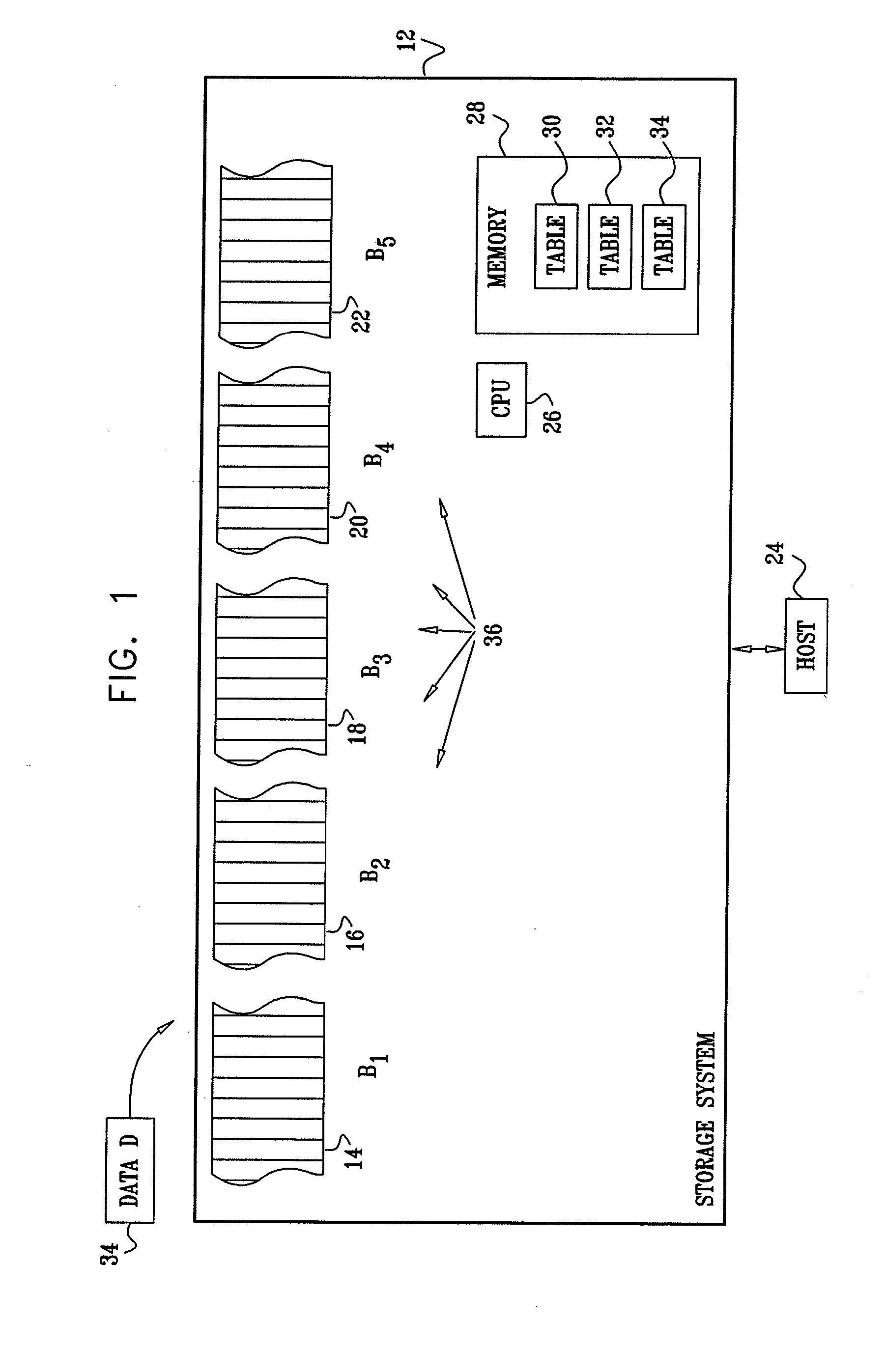
[0155] Reference is now made to FIG. 1, which illustrates distribution of data addresses among data storage devices, according to an embodiment of the present invention. A storage system 12 comprises a plurality of separate storage devices 14, 16, 18, 20, and 22, also respectively referred to herein as storage devices B1, B2, B3, B4, and B5, and collectively as devices Bn. It will be understood that system 12 may comprise substantially any number of physically separate devices, and that the five devices Bn used herein are by way of example. Devices Bn comprise any components wherein data 33, also herein termed data D, may be stored, processed, and / or serviced. Examples of devices Bn comprise random access memory (RAM) which has a fast access time and which are typically used as caches, disks which typically have a slow access time, or any combination of such components. A host 24 communicates with system 12 in order to read data from, or write data to, the system. A processor 26 use...


PUM


Abstract

A method for storing data, consisting of distributing a first plurality of groups of logical addresses among one or more storage devices in a storage system, receiving a second plurality of data-sets containing the data to be stored, and assigning each data-set among the plurality of data-sets a random number chosen from a first plurality of different numbers. The method further consists of partitioning each data-set into multiple partitions, so that each partition among the multiple partitions receives a sequential partition number, assigning each partition within each data-set to be stored at a specific group of logical addresses in the storage system in accordance with the sequential partition number of the partition and the random number assigned to the data-set, and storing each partition in the storage system at the assigned specific group of logical addresses.

Description

RELATED APPLICATIONS [0001] This application is a continuation-in-part to application Ser. No. 10 / 620,080, titled “Data Allocation in a Distributed Storage System” and to application Ser. No. 10 / 620,249, titled “Distributed Independent Cache Memory,” both filed 15 Jul., 2003, which are incorporated herein by reference.FIELD OF THE INVENTION [0002] The present invention relates generally to data storage, and specifically to data storage in distributed data storage entities. BACKGROUND OF THE INVENTION [0003] A distributed data storage system typically comprises cache memories that are coupled to a number of disks wherein the data is permanently stored. The disks may be in the same general location, or be in completely different locations. Similarly, the caches may be localized or distributed. The storage system is normally used by one or more hosts external to the system. [0004] Using more than one cache and more than one disk leads to a number of very practical advantages, such as p...

Claims


Application Information

Patent Timeline
Patent Type & Authority Applications(United States)
IPC IPC(8): G06F12/08G06F11/00
CPCG06F3/0607G06F2206/1012G06F3/0631G06F3/0632G06F3/0635G06F3/0644G06F3/0647G06F3/067G06F3/0689G06F11/2087G06F11/2094G06F12/0813G06F12/0866G06F17/30194G06F17/30584G06F3/0613G06F16/182G06F16/278
Inventor ZOHAR, OFIRREVAH, YARONHELMAN, HAIMCOHEN, DRORSCHWARTZ, SHEMER
Owner INT BUSINESS MASCH CORP
Why Eureka
Try Eureka